
The Magneto is a product of Bendix magneto division and aviation corporation Sydney N.Y. made in the USA made to Specification AN9511A 053AC286 the manufactures drawing number is 10-20700-1 Magneto type SF9LN-4 W30 ELECTRICAL OPERATION.
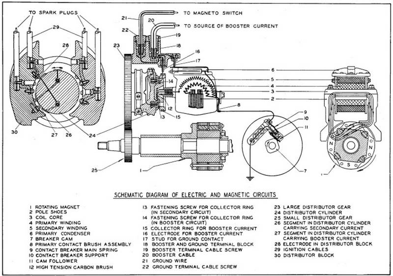
This section is presented to assist readers in understanding the electrical operation of Scintilla magnetos. The rotating magnet has four poles of alternate polarity. Each time the magnet rotates through a quarter turn, the polarity changes and causes the magnetic flux to flow in the oppo- site direction through the core of the coil. This reversing flux causes an alternating current to flow in the primary winding. Energy is stored in the magnetic circuit when the current flows in the primary winding.
The contact points are in series with the primary winding. When the maximum energy has been stored in the magnetic circuit, the cam lifts the cam follower which in turn separates the contact points. This breaks the primary circuit and causes a rapid change of flux in the magnetic circuit. This flux links the secondary winding which has many turns of fine wire. The rapid change of flux due to the opening of the contact points produces the high tension spark in the secondary winding.
One end of the primary winding is connected to the ground. The other end takes an insulated path through the contact points and then back to the ground. The condenser is connected across or in parallel with the contact points and absorbs the current produced by the self-inductance of the primary circuit during the time the contact points are open, thereby pre INSTALLATION venting current from arcing across the points which would cause burning and pitting of the points.
One end of the secondary winding is grounded and the other end terminates at the high tension carbon brush. The high tension spark then goes from the high tension carbon brush to the centrally located segment in the booster collector ring. From here, it is conducted through one of the screws which hold the booster collector ring and then to the high tension segment on the distributor cylinder. The spark then jumps to the distributor block electrodes and through the spark plugs and back to the ground.
The booster current comes through the booster cable which is connected to the booster terminal marked "H." From here, the current goes to the booster electrode, booster collector ring, and through one screw which secures the booster collector ring. It then is conducted to the booster segment in the distributor cylinder and across to the distributor block electrodes and spark plugs. The booster segment in the distributor cylinder trails the high tension segment and consequently gives a retarded spark.
The cable from the magneto switch is connected to the terminal marked "P" which is connected to the ground contact stud and the primary bridge of the coil. When the switch is in the "OFF" position, the primary current is not interrupted by the opening of the contact points. Thus the production of high voltage in the secondary is prevented.
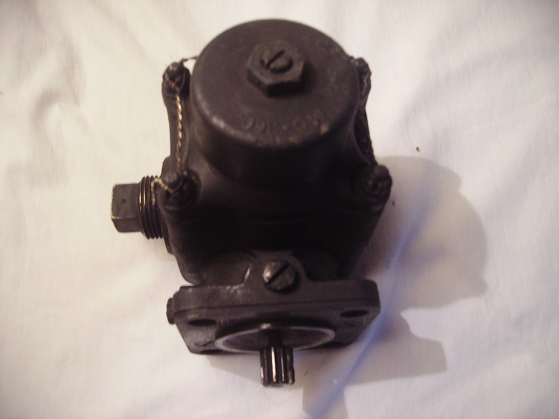
 On The Top Left is The Magneto Output
  The Mechanical Drive Shaft.
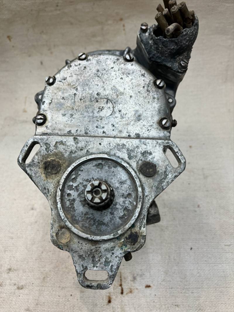
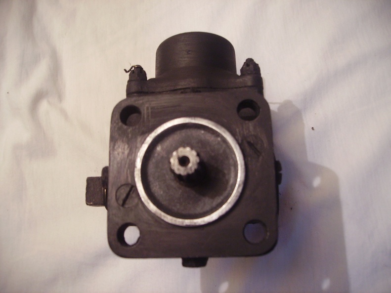
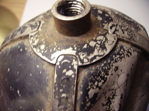
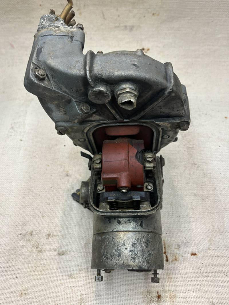 The Bottom of The Magneto.
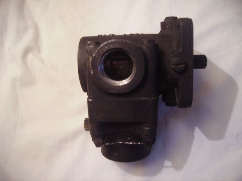
 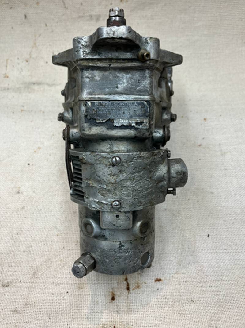 The Side of The Magneto Showing The Output Cables on
 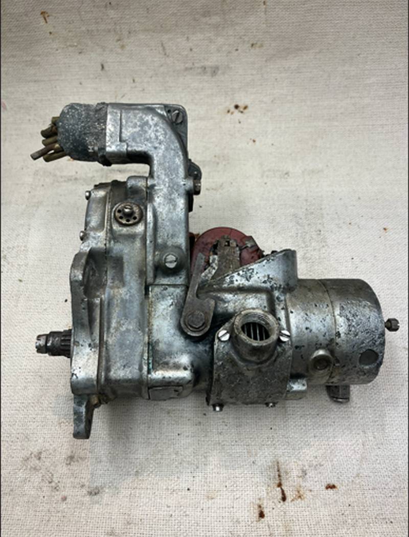 Close Up Details of The Contact Point's.
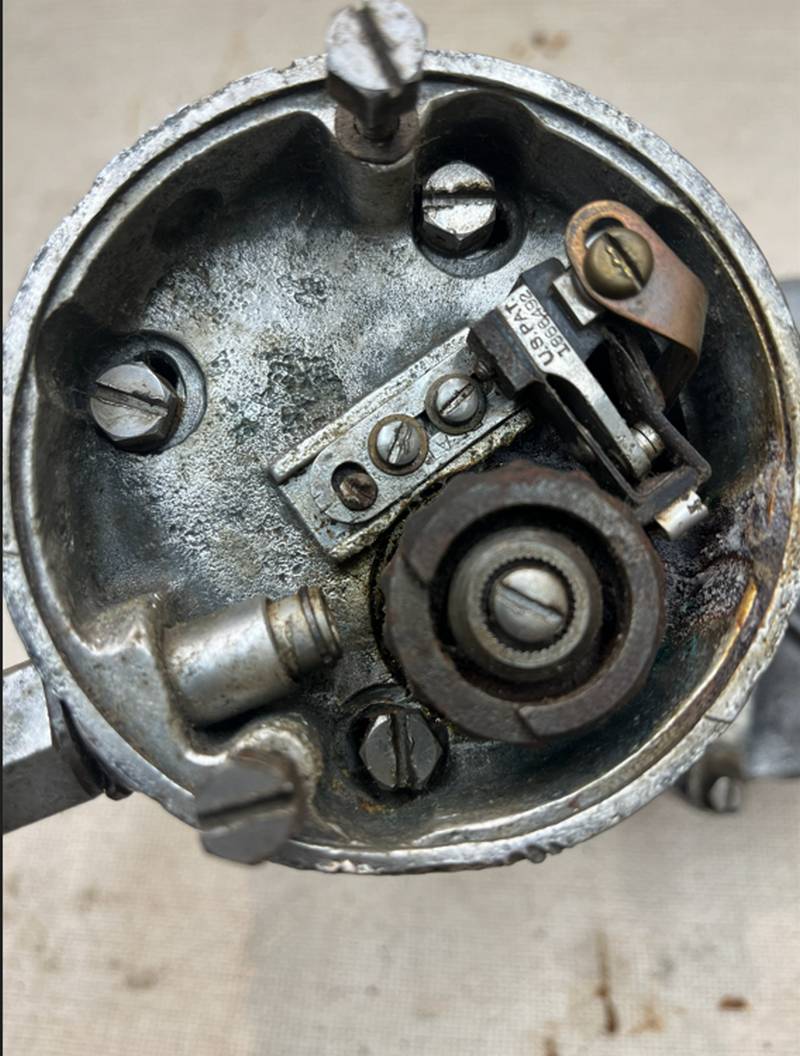 The End of The Magneto With The Contact Point's Cover Removed.
 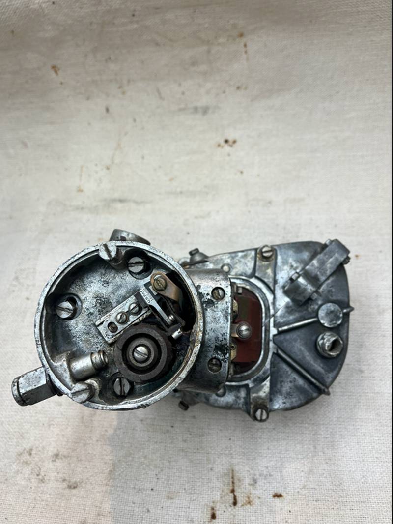 Close Up of The Magneto Coil With The Cover Removed.
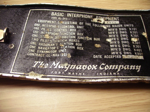
 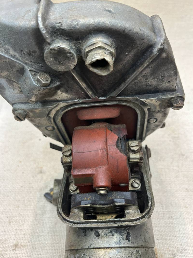 Close Up of The Scintilla Magneto Data Plate.
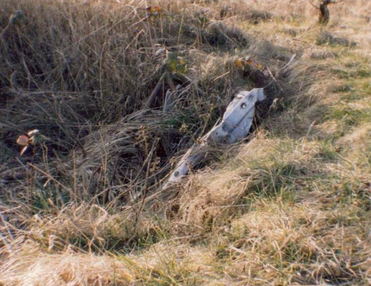
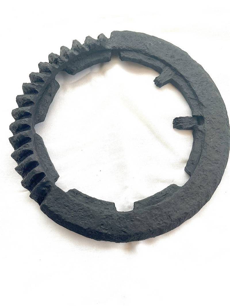
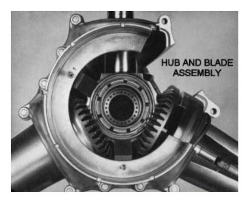
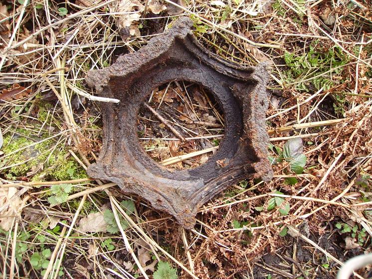
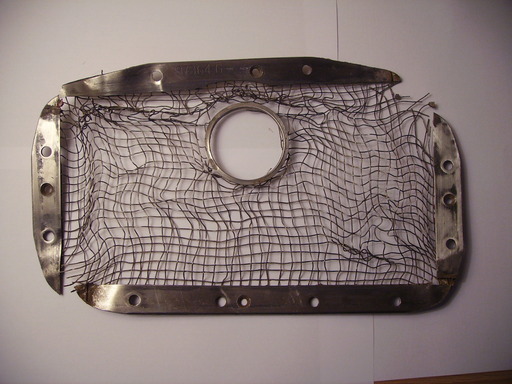
 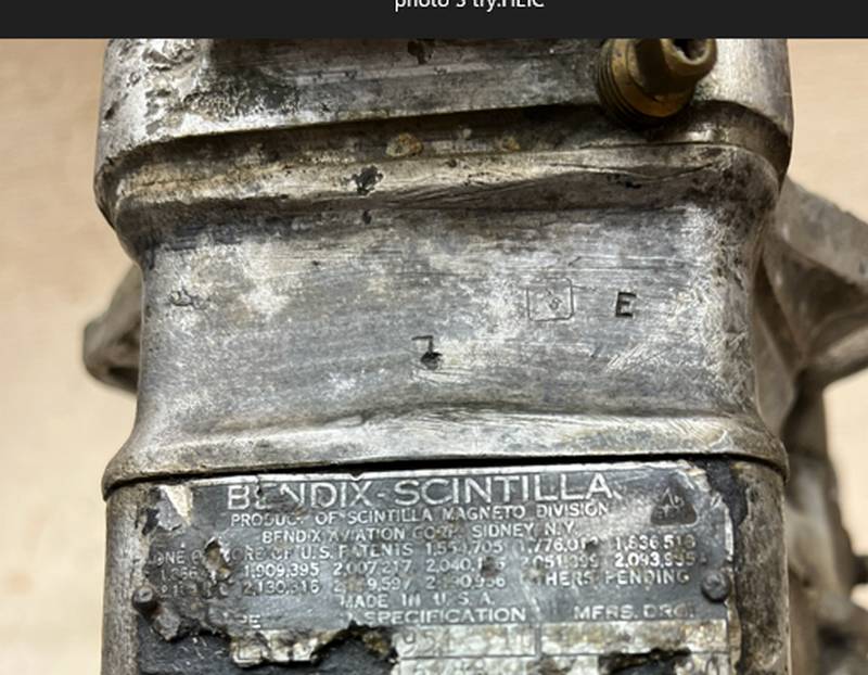 Found on the Mary Ann Site at RAF Burtonwood is a Hamilton
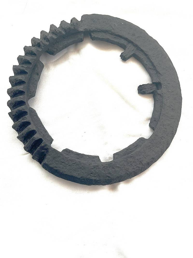
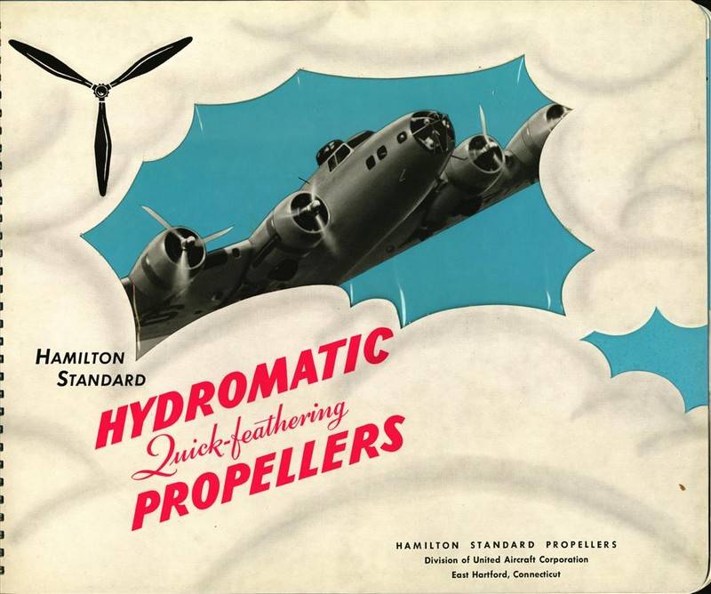
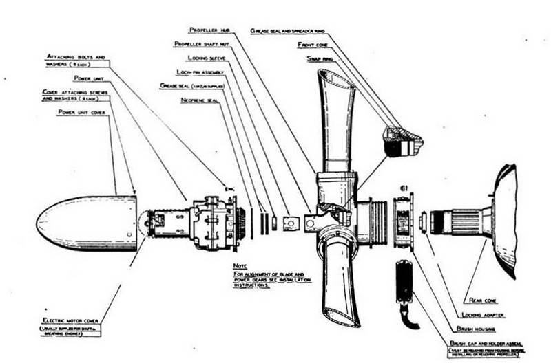
Hamilton Standard became the primary propeller manufacturer for the Allies during World War II. Virtually the entire front-line inventory, from multi-engine bombers to fighter and transport aircraft, as well as a significant majority of RAF aircraft, employed Hydromatic propellers.
Hamilton Standard and its three licensees--refrigerator manufacturers Frigidaire and Nash-Kelvinator, and office equipment maker Remington-Rand--produced 530,135 Hydromatic propeller assemblies during the war. Vintage advertisement for Hamilton Standard Hydromatic Quick-feathering Propellers.
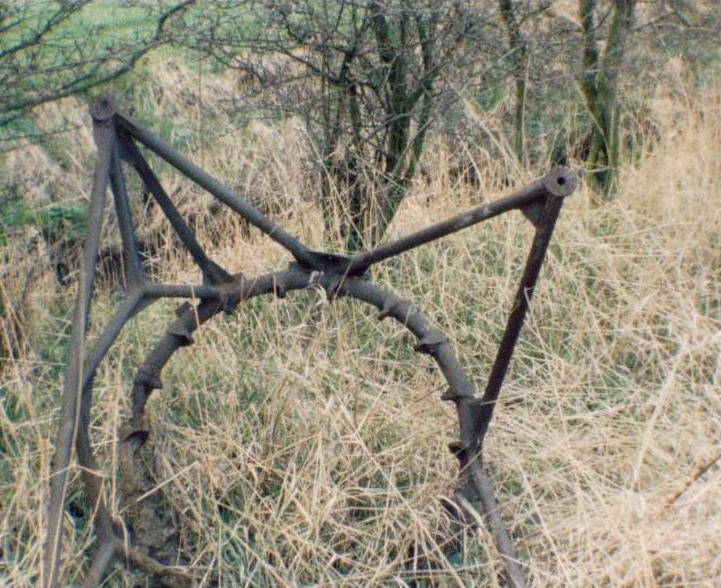
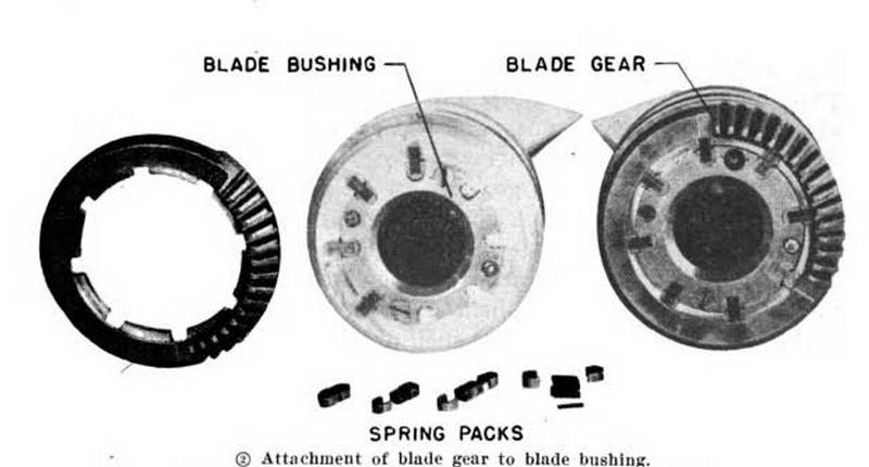
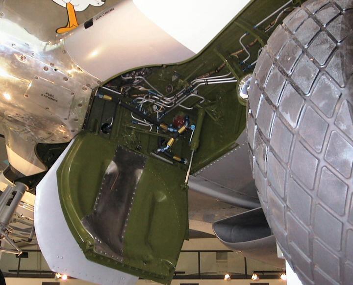
The Hamilton Standard propeller blade gear segment located at Burtonwood is driven by a rotating cam, which is actuated by a hydraulic piston inside the propeller hub. The piston's forward or aft movement, controlled by the governor and engine oil pressure, causes the cam to rotate clockwise or counter-clockwise, respectively, thereby turning the blade gears and changing the blade angle (pitch).
attached to the base of each of the propellers
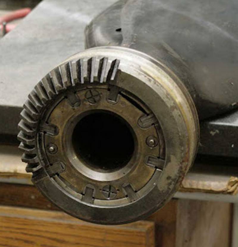
distribution valve and rotating cam gear.
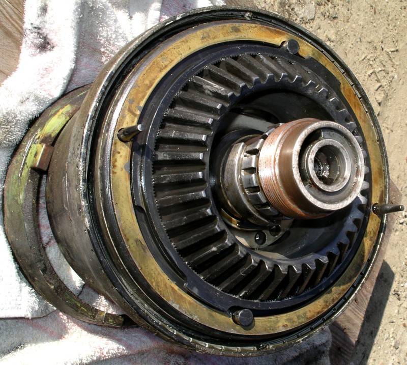
speed, selective pitch, and feathering, propellers.

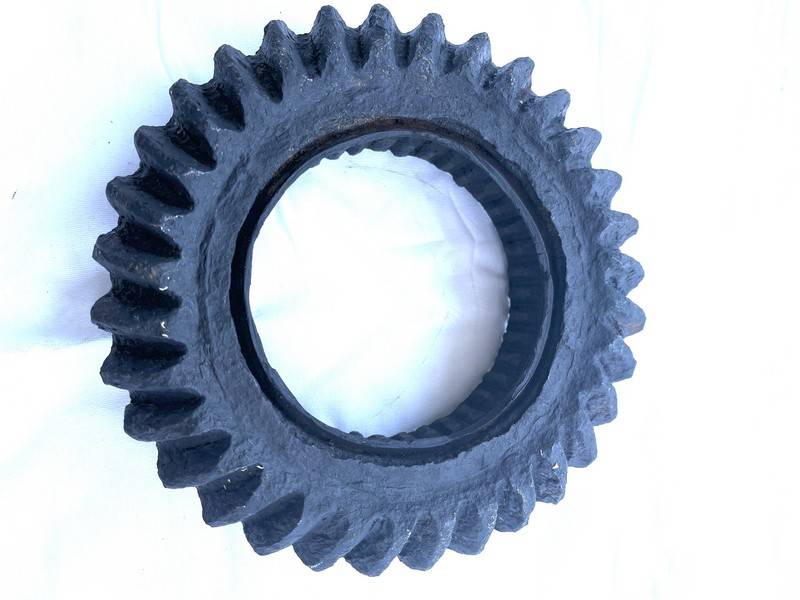
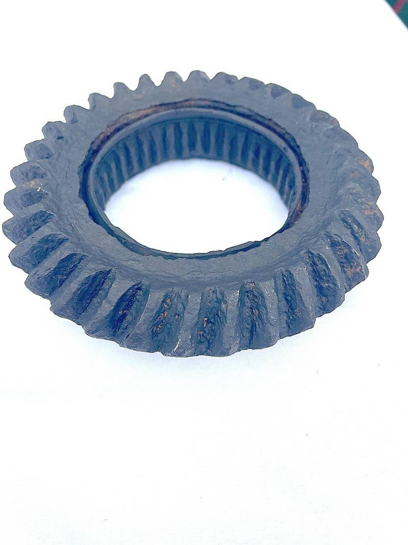
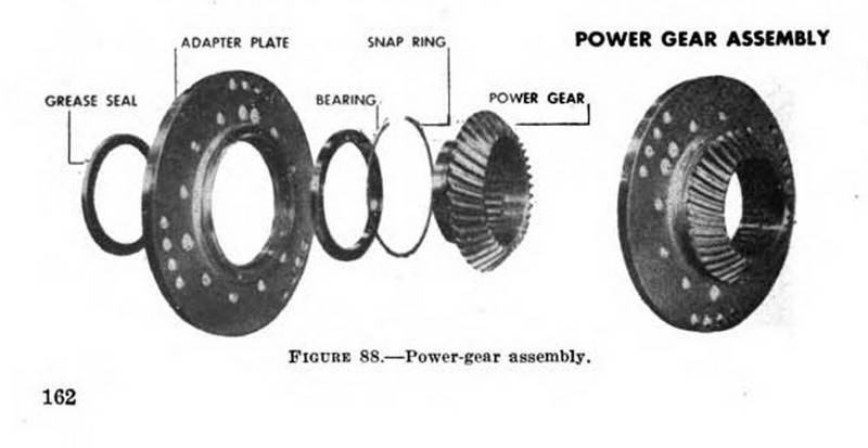
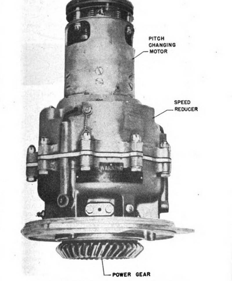
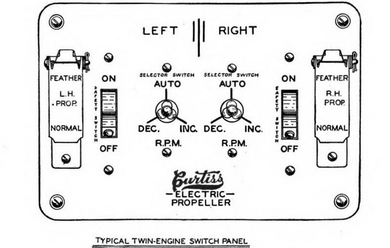
The Method of the Curtiss pitch control.is an Electrical system that is a small, reversible electric motor that regulates the blade angle change of the Curtiss electric propeller. The electric current for operating this motor is obtained from the airplane's power battery.
This motor, through a series of gears, drives a power gear that in turn meshes with a gear attached to the shank of each blade. The electric motor, reduction gears, and power gear are part of a compact unit called the power unit, which is mounted on the front face of the hub. Curtiss propeller power gear that was found at RAF Burtonwood
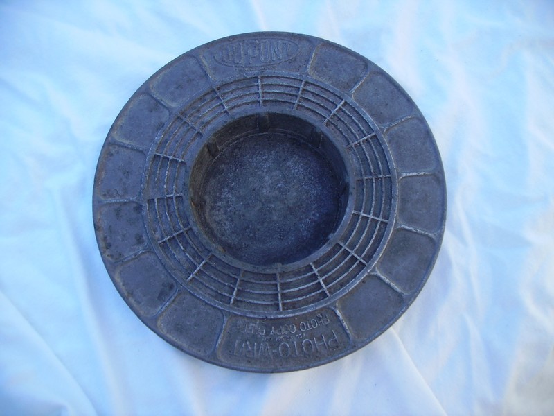
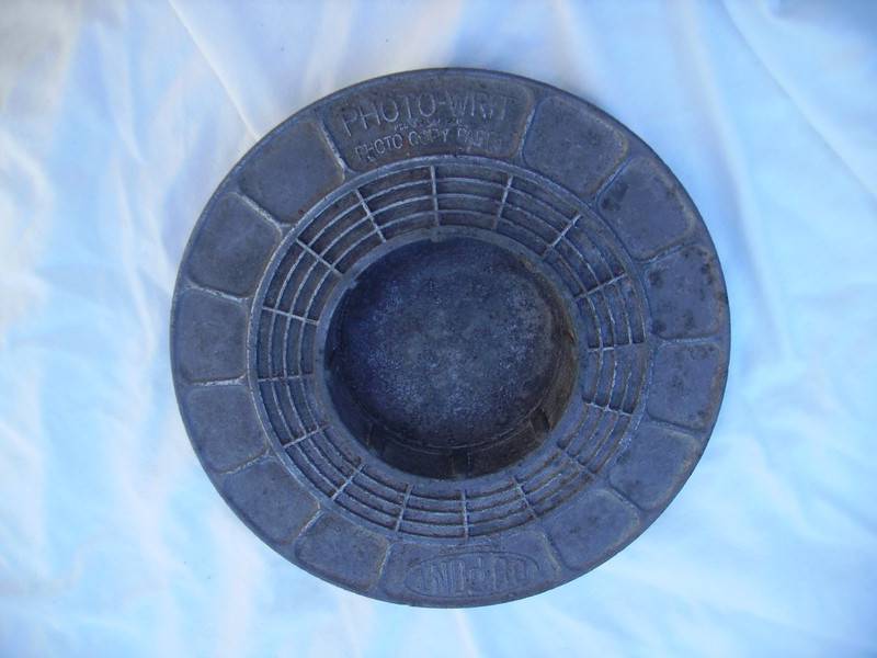
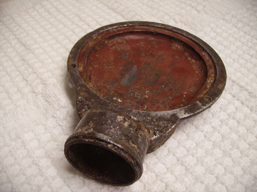
This ash tray/change dish advertisesthe photo writ photocopy paper.Dimensions: 6.5" diameter x 1" high.Weight: 9.2 Oz.
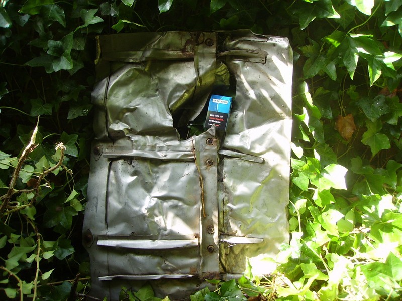
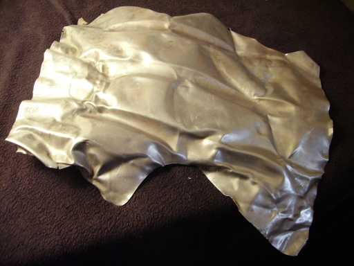
Chute Found 5th of October 2014
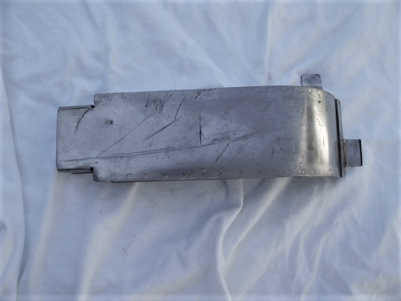
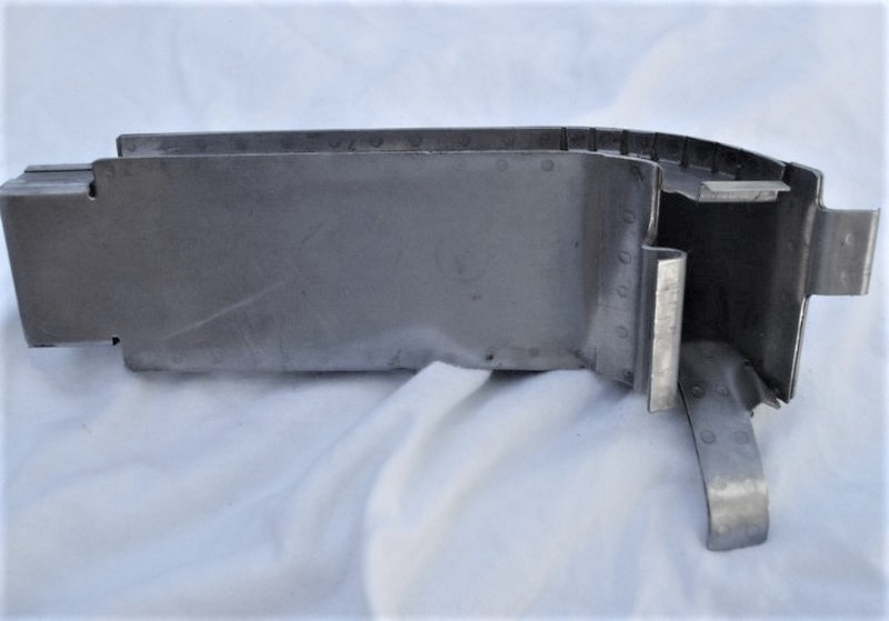
No Factory Numbers or Part Numbers Visible
Designed by MC Manufacturing Company Detroit Found at Burtonwood 10th of May 2015
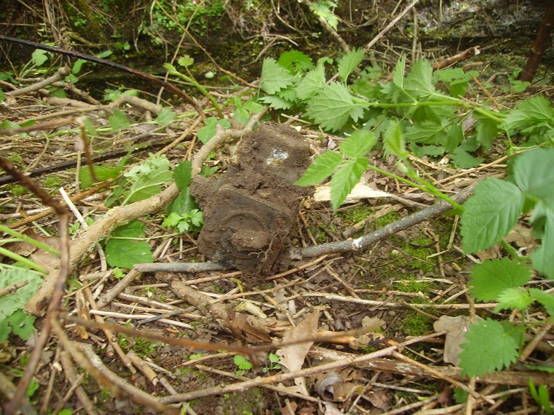
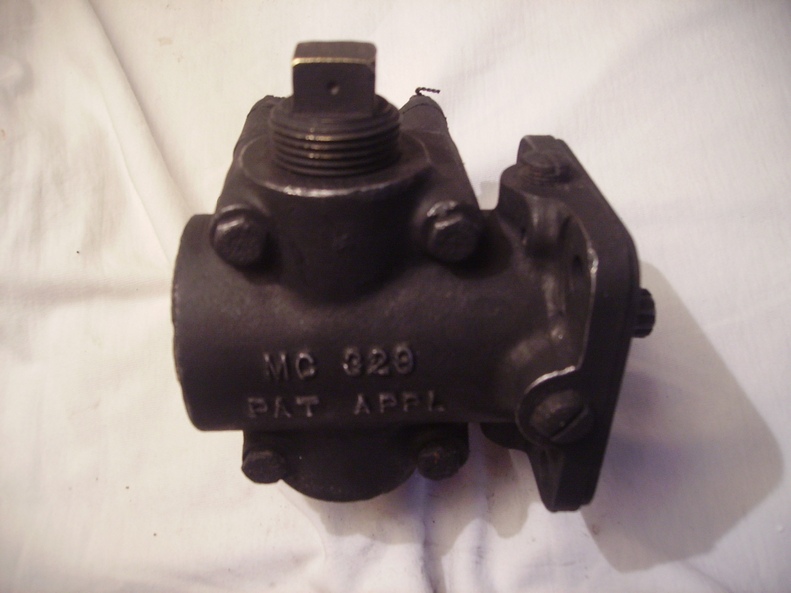
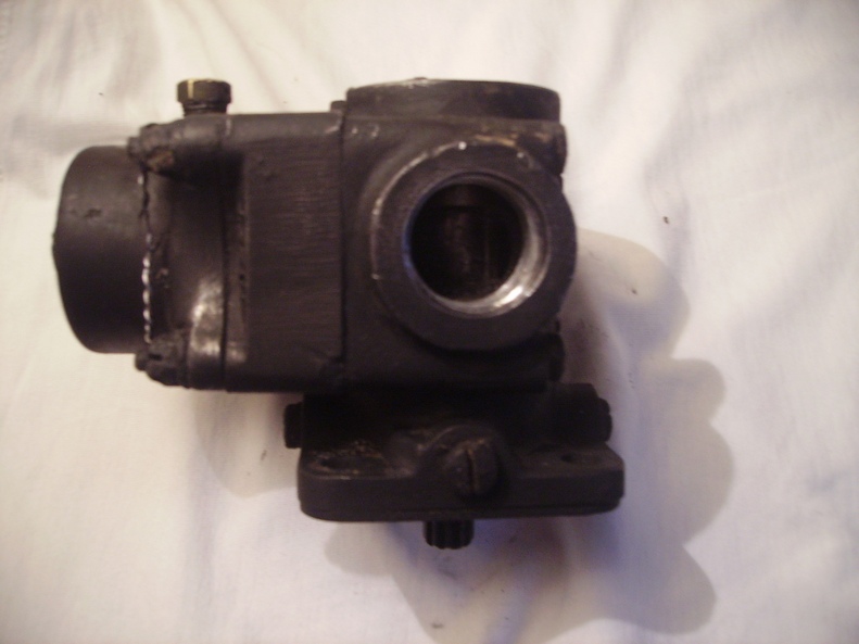
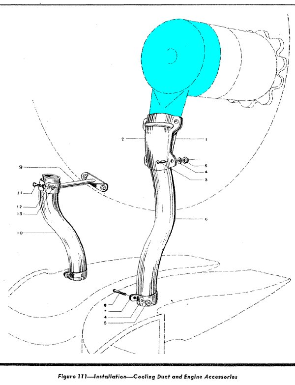
to a Stromberg PD-12H2 Carburettor
machine gun manufactured in this case by Emerson.
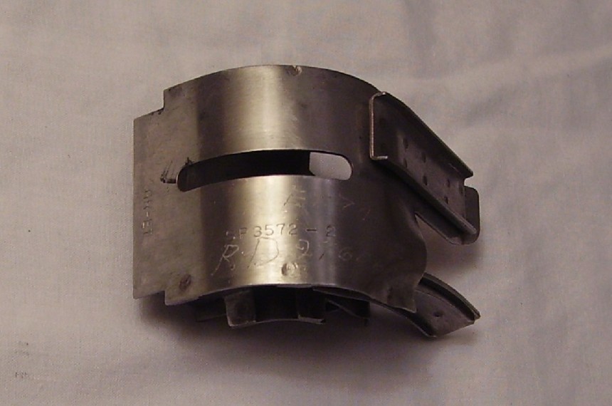
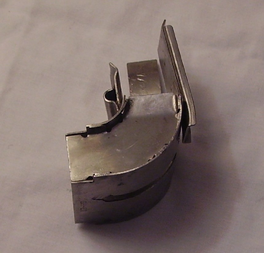
Part Found at Burtonwood 5th of October 2014?
There are a variety of numbers engraved and stamped on this item.
There is:
GR-ET
SP 3572 - 2
RD24606
ET740E
Thanks again to Paul Bellamy for the Info.
Found at Burtonwood 5th of October 2014
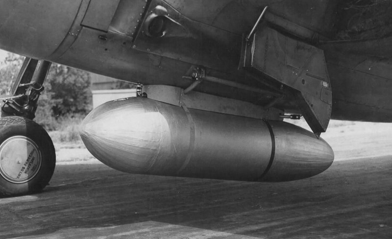
and then installed in the bomb bay.
by an electrical release unit to drop the bomb.
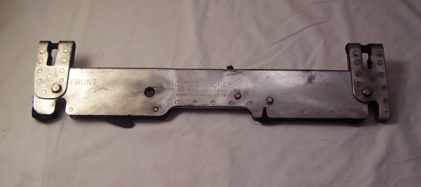
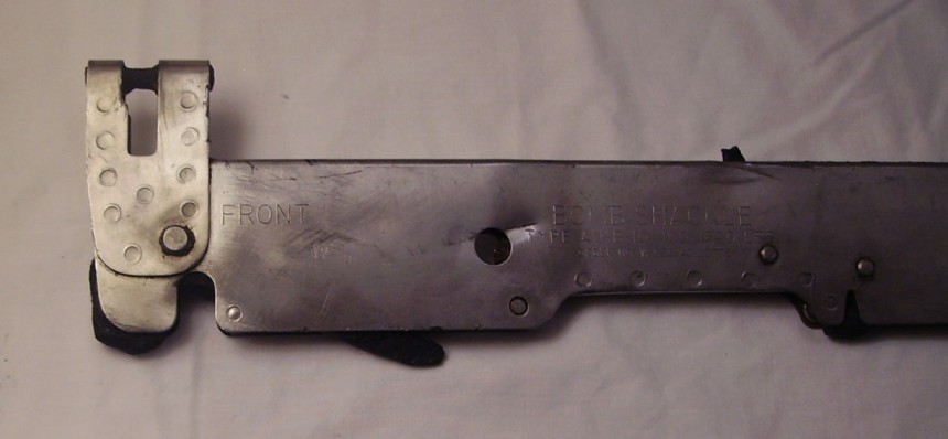
Order Number W-535-AC-27778 (on the left hand side) 43D10158 (on the right hand side lower down)
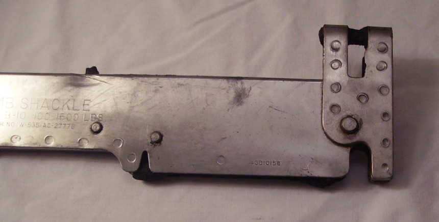
Found on the 30th of March 2014 at Burtonwood
Part number: 4138119
(546 is also above that number)
Any ideas of which aircraft this is from?
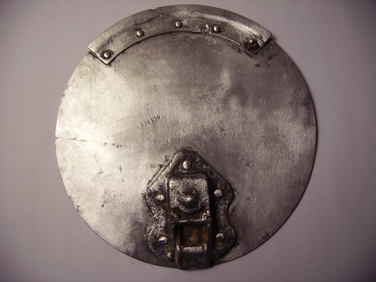
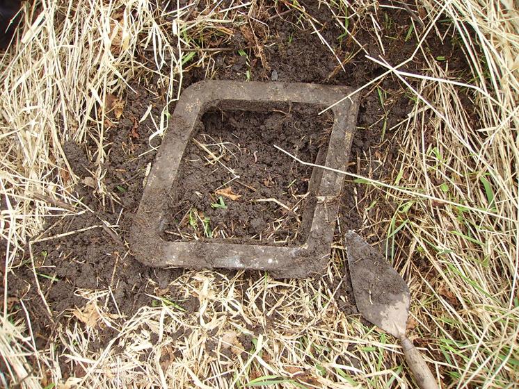
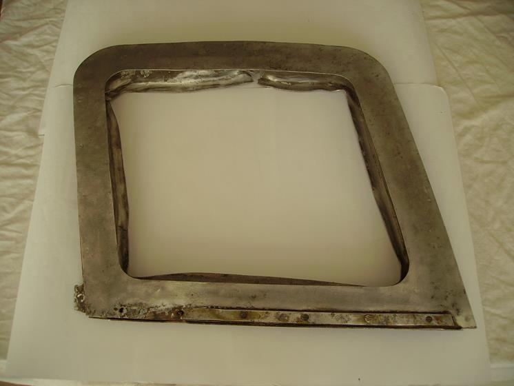
Filler Port (flap) Cover (inside) part number: 4138119 (546 is also above that number in a sort of square shape) Any ideas of which aircraft this is from?
2014 at Burtonwood
There is some writing in ink on this but we cannot make it out clearly?
It looks like it says:
'Fuel Tank Filler'
Any ideas of which aircraft this is from?
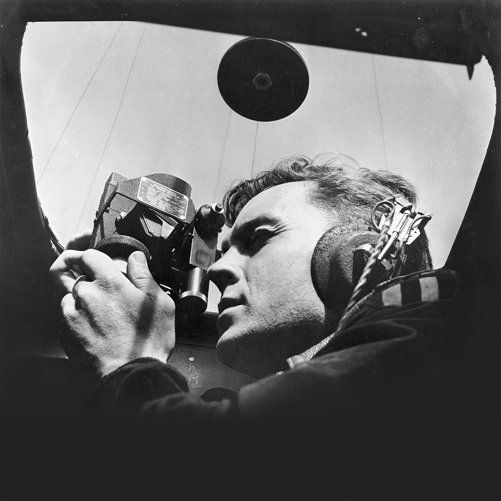
4" Disk - Bolted to Plexiglass Found on the 30th of March 2014 at Burtonwood
Found on the 30th of March 2014 at Burtonwood
This part is built into the roof of the navigators astrodome & the centre metal has an inside thread to support the weight of a navigators sextent. This was sometimes used because the sextent was quite heavy to hold.
Found on the 23rd of March 2014 at Burtonwood Any ideas of which aircraft this is from?
Found on the 23rd of March 2014 at Burtonwood The part number in a circle is 138 Any ideas of which aircraft this is from?
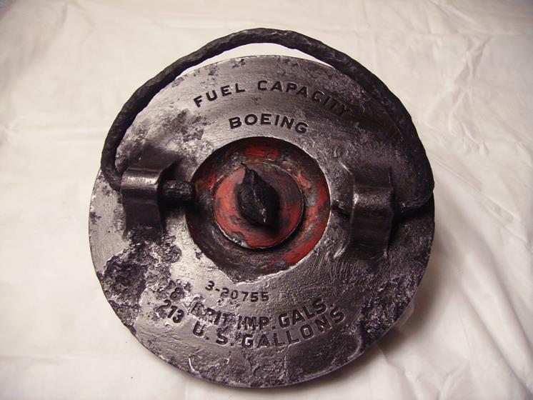
Found on the 19th of January 2014 at Burtonwood Part Number: 3-20755
(Found at Burtonwood Today 18th of August 2013)
The Part Numbers Stamped On it are:
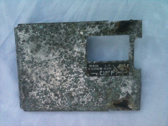
24 (in a circle) 32E1503-6
Assembly Number 32E1503
Faint ink stamp with date May 25th 1944
Faint Number is 195
Thanks to Paul Bellamy For Identifying the part as:
32E1503-6
32= B-24 Liberator E = Electrical system Other than that, it's the 6th part of sub-assembly 1503
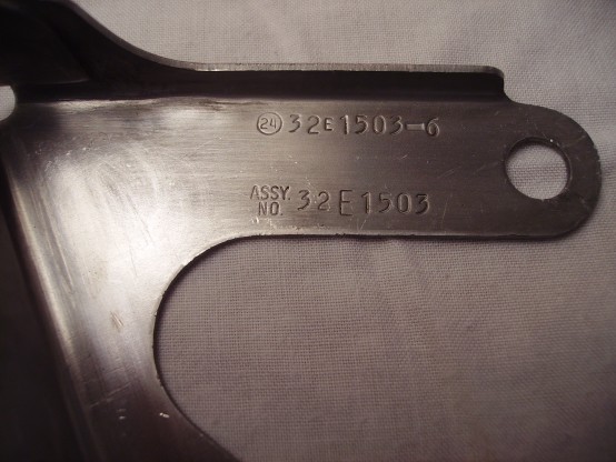
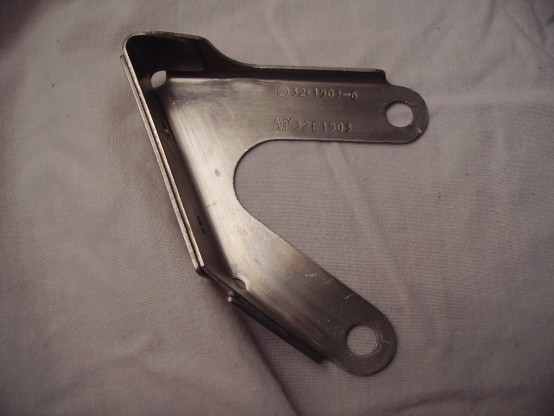
It is a Main Switch For 'Gun Off'
Left Hand & Right Hand 'Gun Off'.
The Part Numbers Stamped
On it On The Reverse Side Are:
T1283
AM
J27
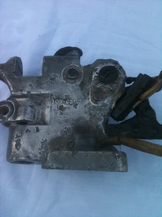
The Part Numbers Stamped On it Are:
109-63117
AN D78 (In a Circle)
Part numbers prefixed 109 are originally for the P-51D.
The casting is a bit corroded, so the number is 109-63117
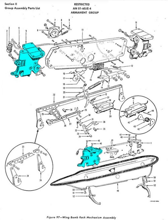
Component part of 109-63218: Mechanism Assembly, Bomb Rack, LH. (Thanks again to Paul Bellamy for his help finding out what this item was for and which aircraft it was fitted on as well)
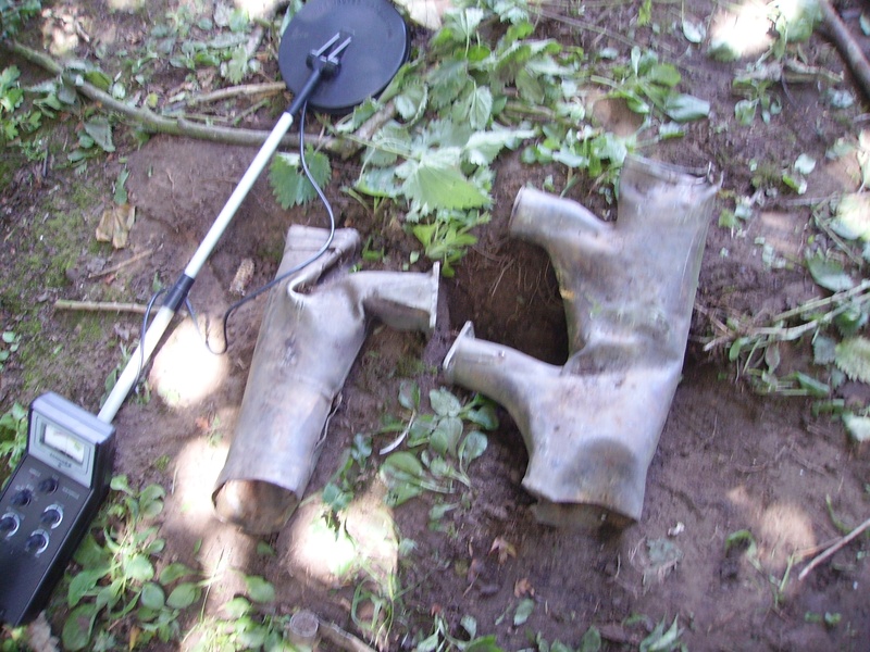
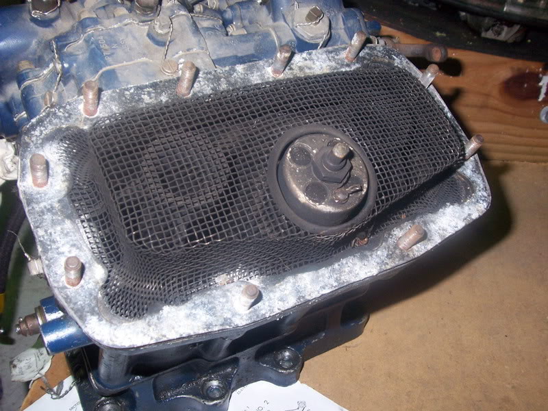
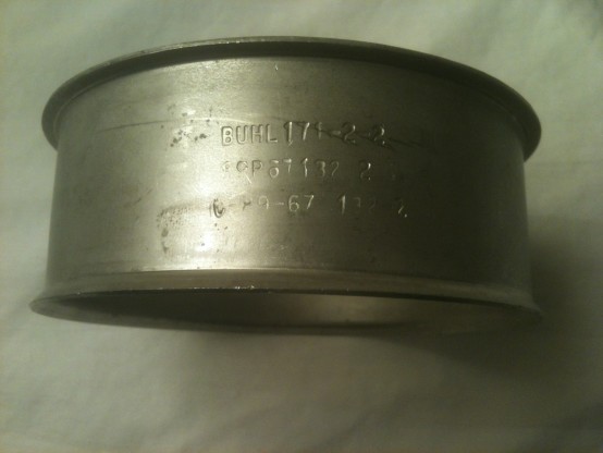
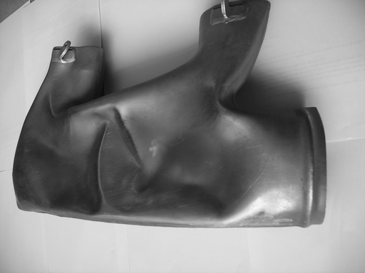
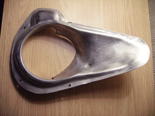
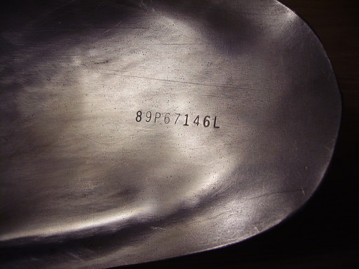
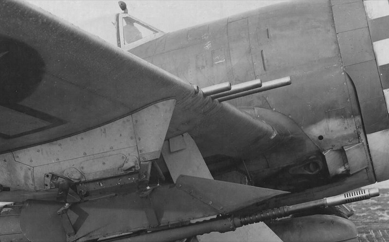
It is a Starboard-Side Exhaust Manifold Sleeve From a P-47 Thunderbolt.
The Part Numbers Stamped On it Are:
BUHL 171-2-2
89P87132 2
C-89-67-132-2
89-prefixed parts are from a P-47. The letter indicates which section of the airframe it belongs in, P = powerplant, i.e. the engines and related items. The next two letters indicate the subsystem, 67 = Installation, Exhaust System. This is a sleeve from a P-47 starboard-side exhaust manifold section joint. The matching sleeve for the port side is 89P67132-3.
23rd of June 2013. (Thanks again to Paul Bellamy for his help finding out what this item was for and which aircraft it was fitted on as well)
System From a P-47 Thunderbolt.
The Part Numbers Stamped On it Are:
BUHL 171-2-9
89P67107
C-89-67-107
We can't find item 89P67107 specifically listed anywhere but, as noted above, the 89P67xxx number means it also has to be part of a P47 exhaust system.
23rd of June 2013. (Thanks again to Paul Bellamy for his help finding out what this item was for and which aircraft it was fitted on as well)
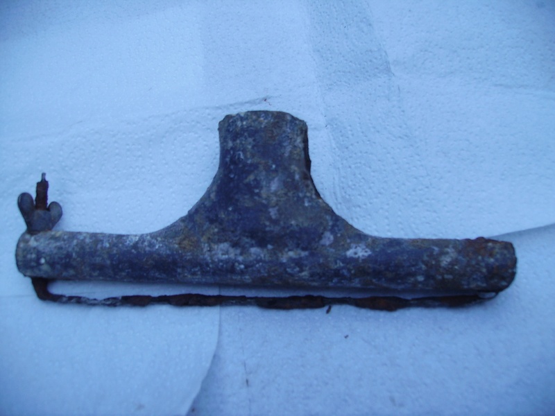
System From a B-24 Liberator.
The Part Numbers Stamped On it Are:
1-2884
SOLAR
32P1721
32-prefixed parts are from a B-24. Again, the letter indicates which section of the airframe it belongs in, thus 32P = B-24 powerplant. This is an exhaust section from between one of the the forward bank of cylinders and the collector ring. Solar is the sub-contractor who supplied this particular part, the Solar Aircraft Co.
23rd of June 2013. (Thanks again to Paul Bellamy for his help finding out what this item was for and which aircraft it was fitted on as well)
Support Rudder Trim Tab Control From a B-17
Boeing
9-5067-1
DH
Found at Burtonwood
16th of June 2013. (Thanks again to Paul Bellamy for his help finding out what this item was for and which aircraft it was fitted on as well)
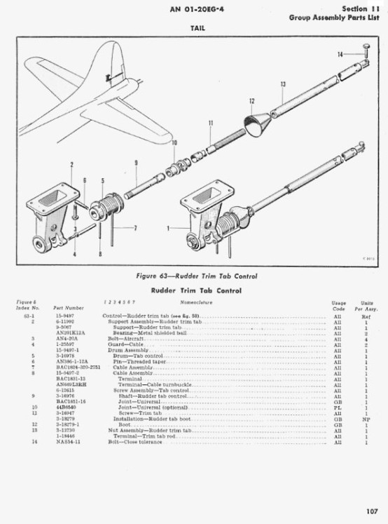
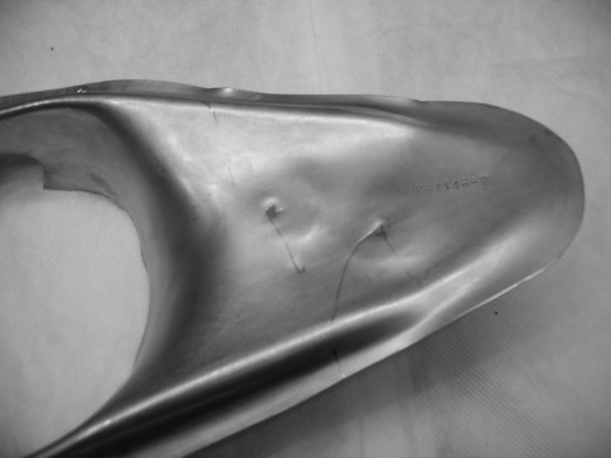
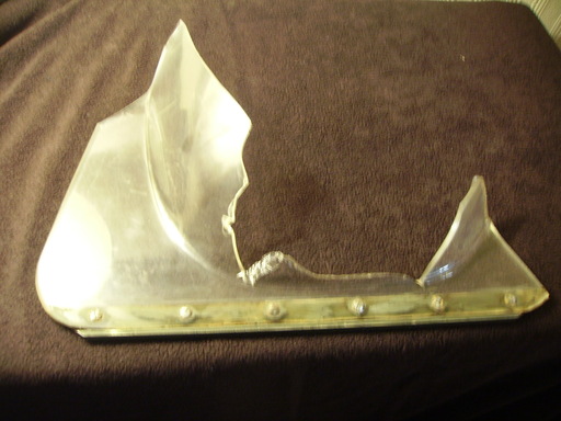
Found at Burtonwood 26th of May 2013. The bulge at the top is to clear the flap operating mechanism, so the post and starboard shrouds are mirror images. Please Note: This one is a starboard one (Right Side) and we found another one of these in 2012 & not far from this newer one, although that one was a portside one (Left Side). More info on the portside one can be found on this page further down.
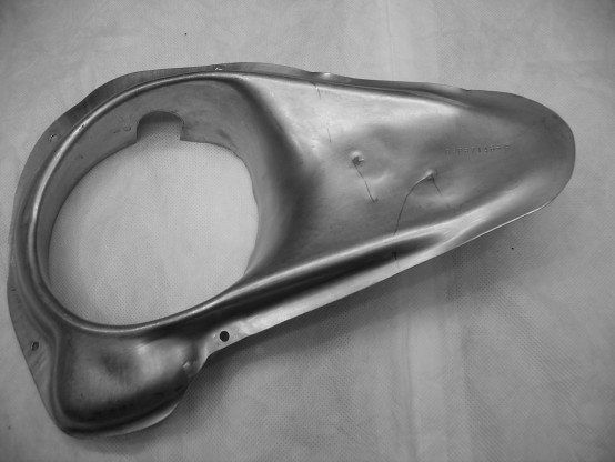
We would just like to mention here that we were contacted by a very proud mum (Jayne) asking us if we could help out with information regarding the history and layout of the USAAF Burtonwood base during WW2. The story goes that after buying a house in the Chapelford area of Warrington Jayne's 12 Year old daughter Megan became extremely interested in the history of the USAAF Burtonwood base.
And after after a few emails to each other Megan & her brother Aaron joined me and Malcolm on the base detecting for WW2 aircraft parts today the 26th of May 2013. Here below is their photo of Megan holding the waste gate shroud in her hands that we all found. Me & Malcolm are very proud of this young girl's interest and we applaud her.

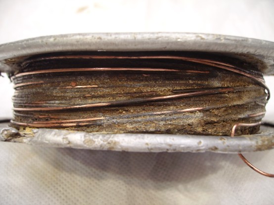
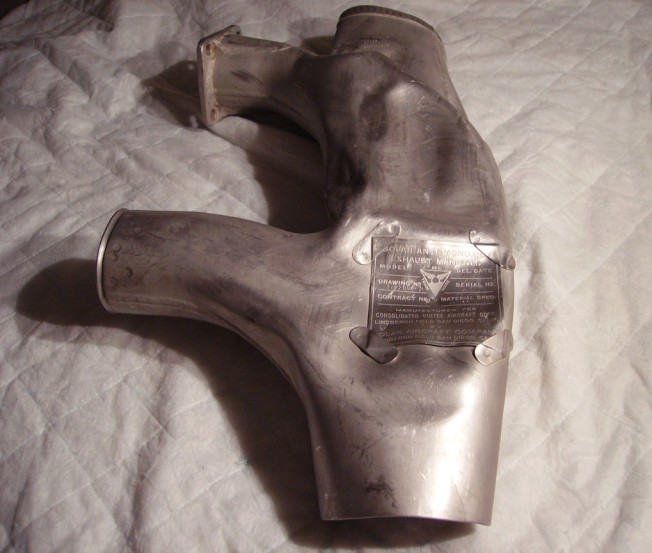
Part Number (stamped in ink in a circle) is:
19
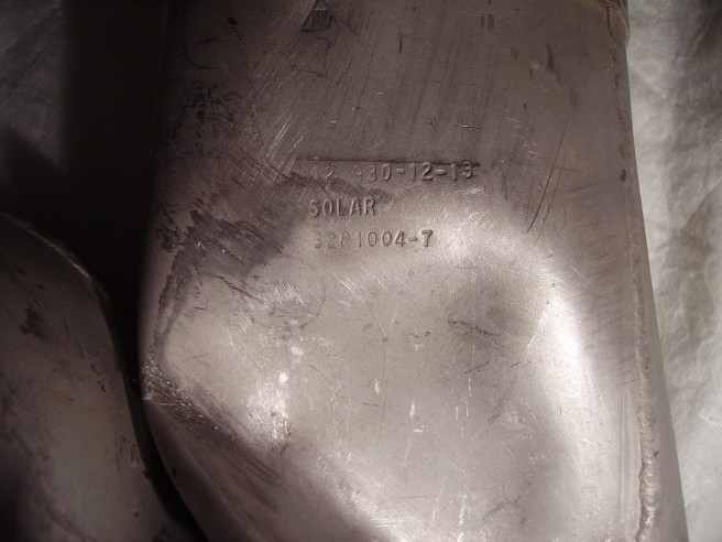
The other serial numbers are:
12 930-12-13
Solar
32P1004-7
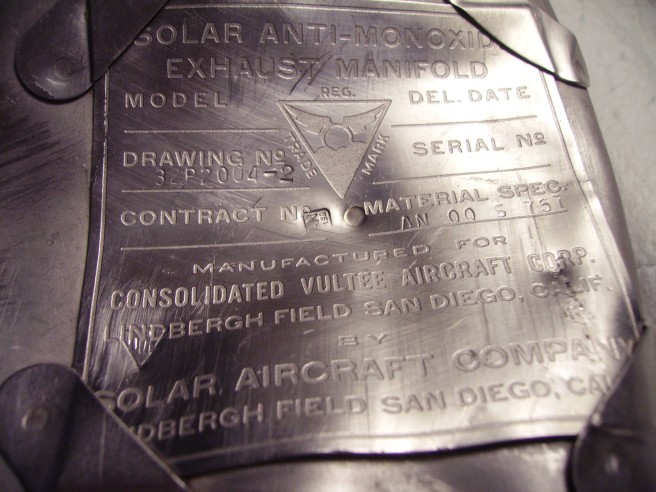
And on the large manufacturers label other numbers & manufacturers info can easily be seen on the 3rd photo.
If you do then email us.
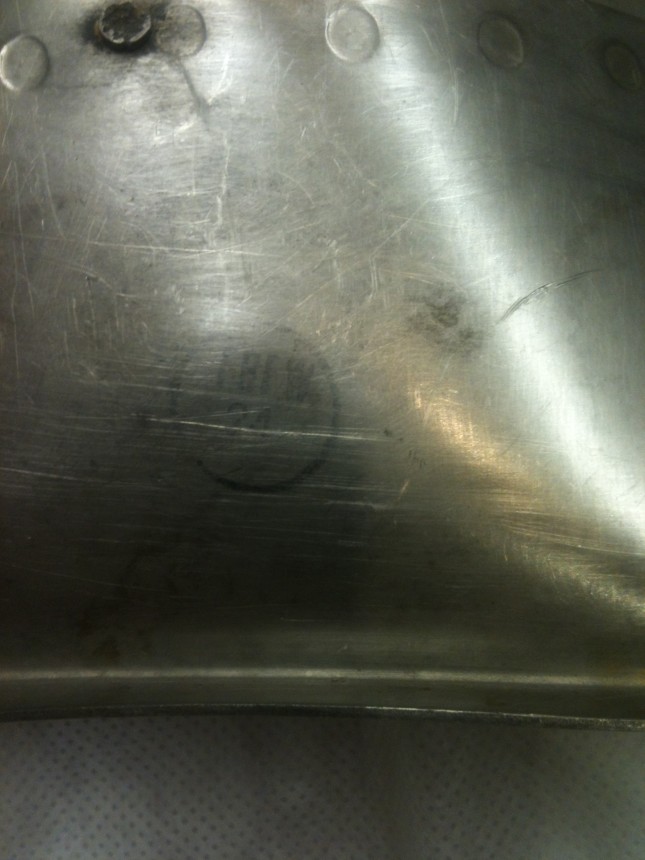
Part Number (stamped in ink in a circle) is:
FBFW 24
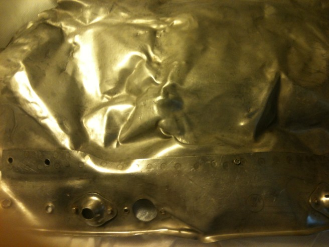
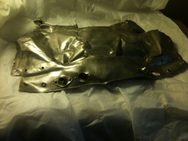
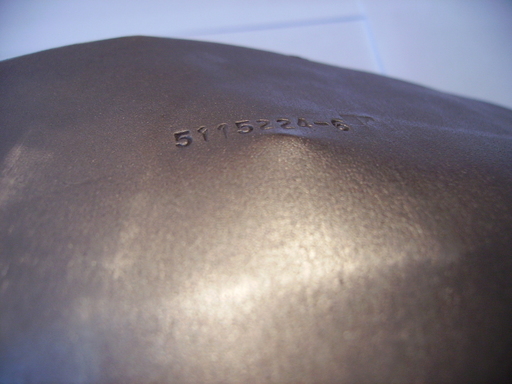
Part Number is:
5115224-6
5115224-6 is the part number for an exhaust collector ring segment for a Pratt & Whitney R-1830 Twin Wasp, particularly for the C-47 and C-119 installations. (Thanks again to Paul Bellamy for his help finding out what this item was for and which aircraft it was fitted on as well)
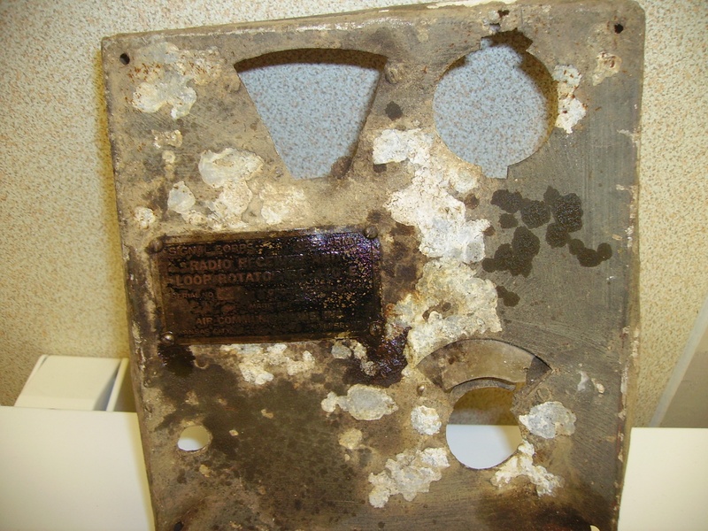
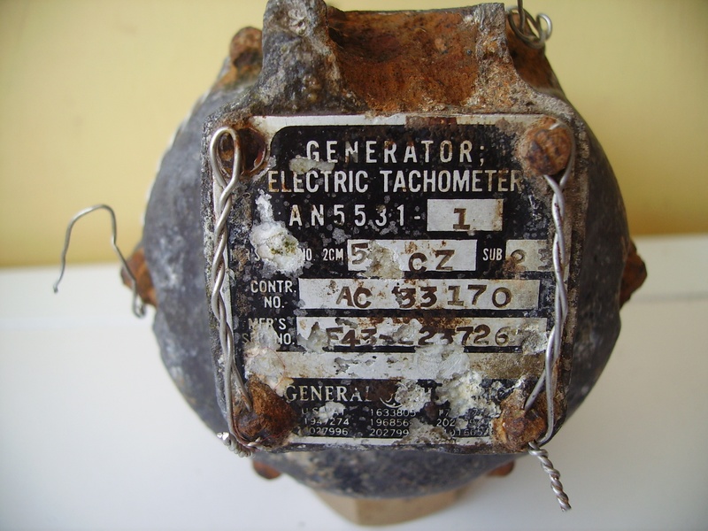
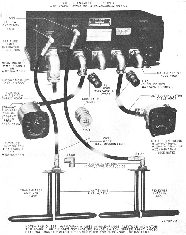
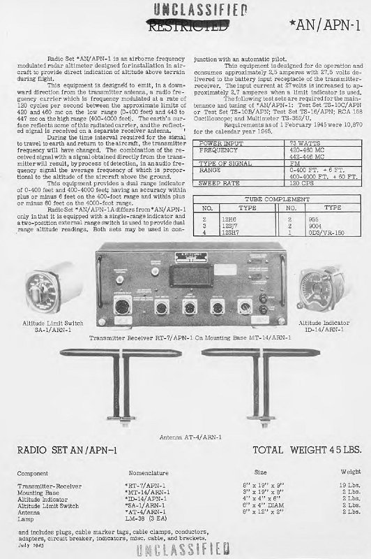
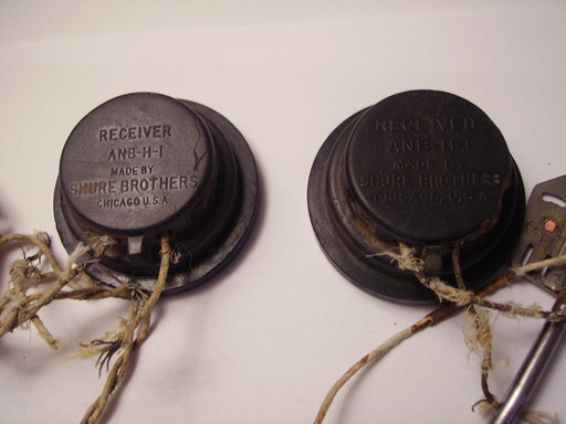
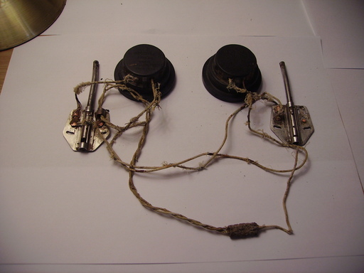
Part of the AN/APN-1 Radio (Radar) Altimeter system: Found at Burtonwood on the 22nd of April 2012. Thanks to Paul Bellamy Regarding The Research of Most of The Items on This Page.
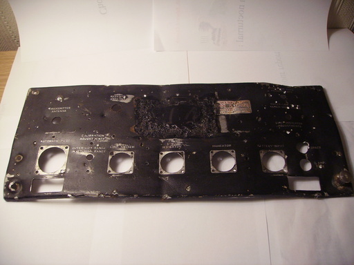
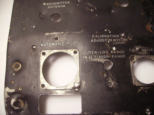
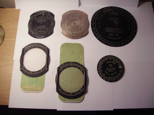
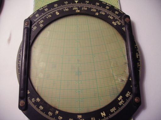
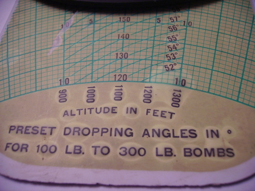
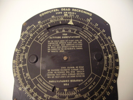
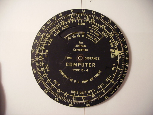
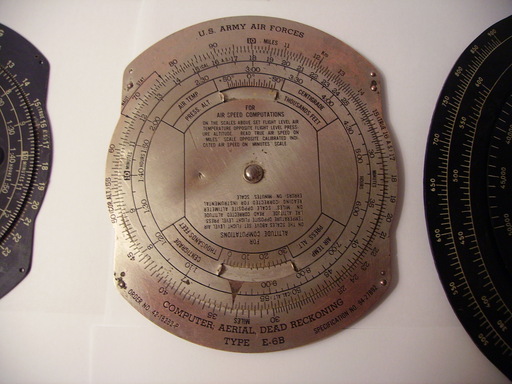
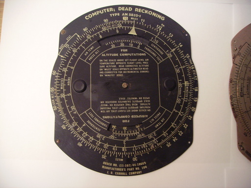
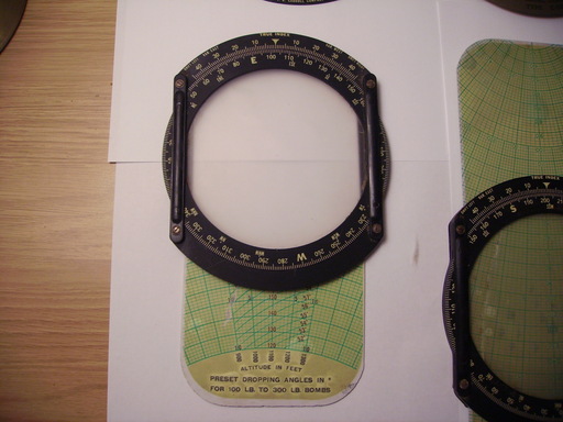
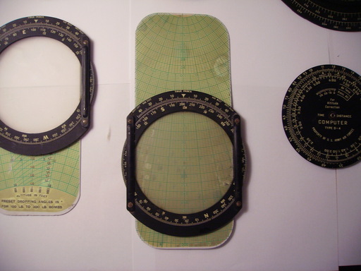
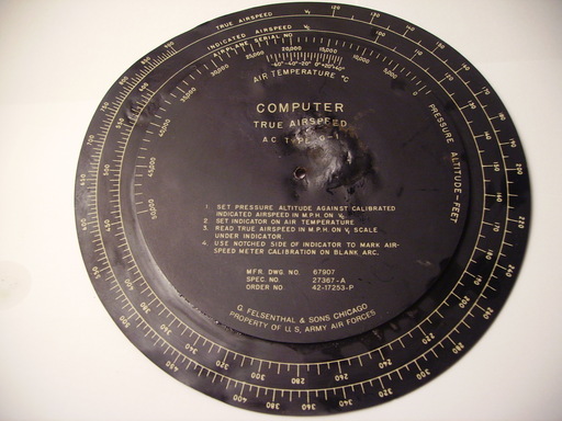
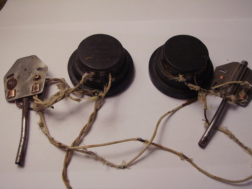
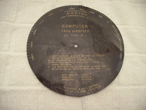
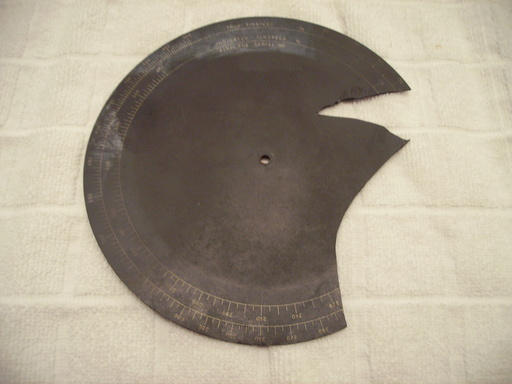
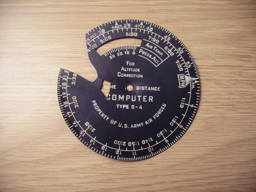
Navigators Instruments All Found Together at Burtonwood.
Please note: We Found Many More Than These But Some of Them Have Parts Missing or Are Slightly Damaged.
Found at Burtonwood on the 1st of April 2012.
Any Ideas?
Numbers on it Look Like:
E432
LARE
214 1/2
Found at Burtonwood on the 11th of March 2012.
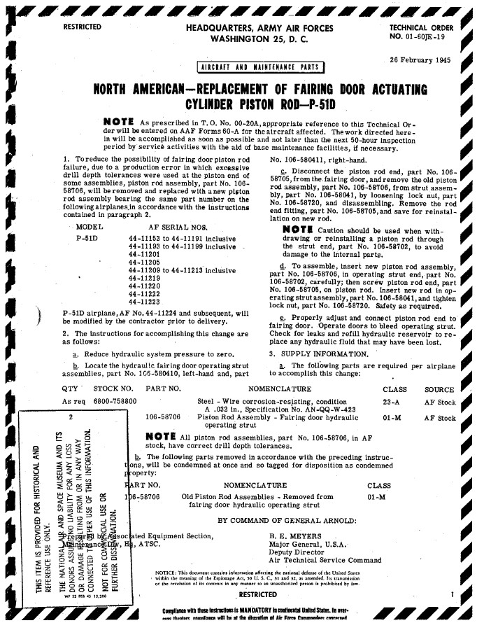
106-58041: Strut Assembly 106-58702: Operating Strut End
Serial No. 10656-2304
Assem 106 58041
E38 106-58702
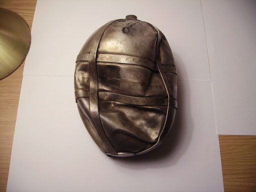
Found at Burtonwood on the 4th of March 2012.
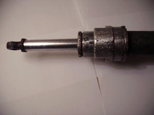
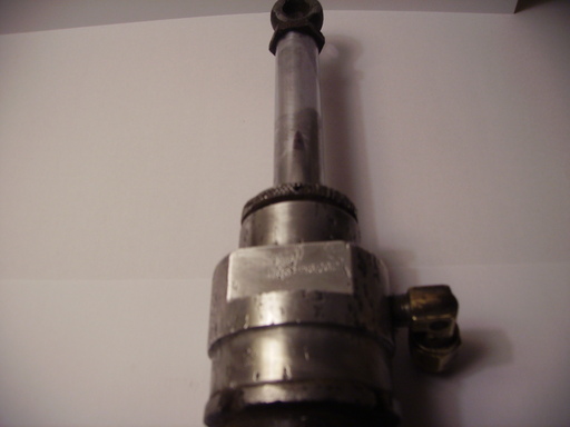
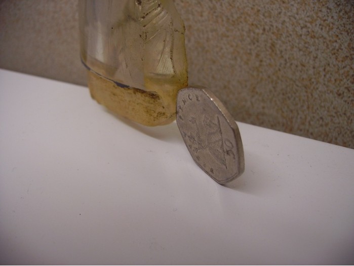
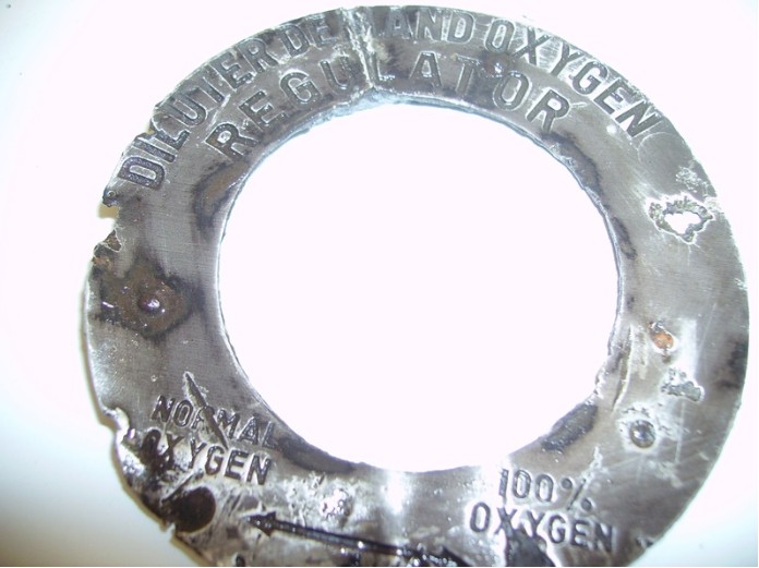
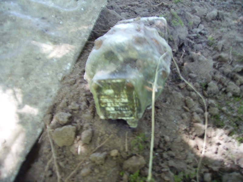
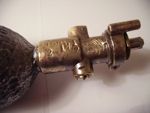
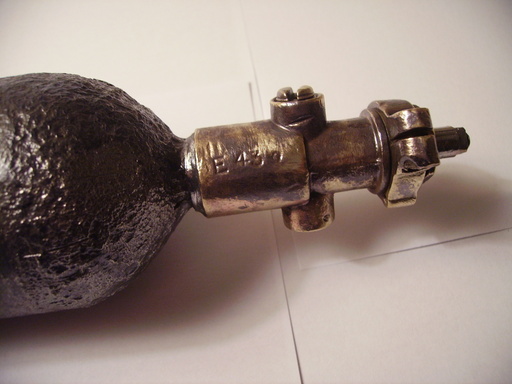
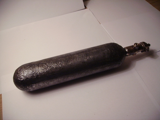
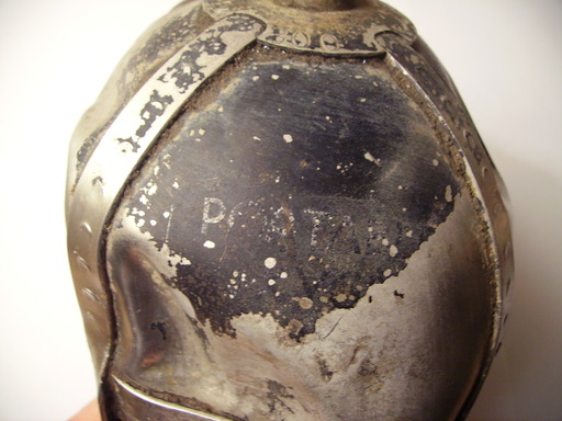
We Thought it Was a Portable Oxygen Bottle Because it Has The Words'POATAB'Written on The Top of The Cylinder (Photo 2 Below). It Also Has These Numbers Imprinted Around The Neck of The Cylinder:
'800 3-43'
Any Ideas What This Item is or ANY of
The Other items Are on our Site?
Contact: [email protected]
It is Obviously an Aluminium Alloy Aircraft Part. The Part Number is: F912-499-63 If You Know What This Part is From Then E-Mail Us .... Found at Burtonwood 23rd January 2012.
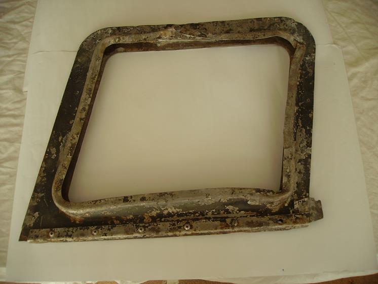
It is a Plexiglass Canopy Part With Olive Green Frame. There is an Identification Symbol On This Part. It Has a Circle WithHTin the Top Half & Some More Letters Beneath it, But We Cannot Make Them Out? Found at Burtonwood 23rd January 2012.
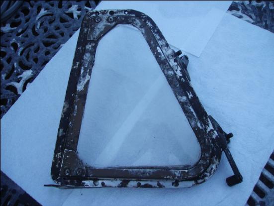
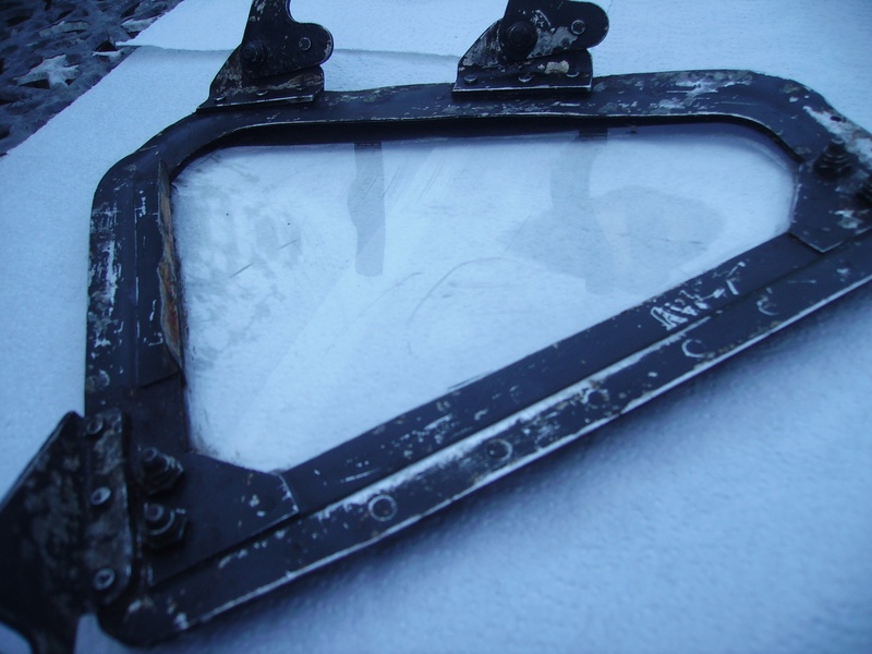
The plexiglass frame is painted olive drab green on the outside & black on the inside, with 2 red-painted levers with catches on, which move up and down a yellow sign with red writing, which reads 'Emergency Use Only'. I have looked on Google images and found an image of the inside of a Liberator B24 & I think it looks exactly the same. Curved Plexiglass. Found at Burtonwood August 2011.