|
Royal Naval Air Station HMS Ringtail
(Burscough Lancashire)
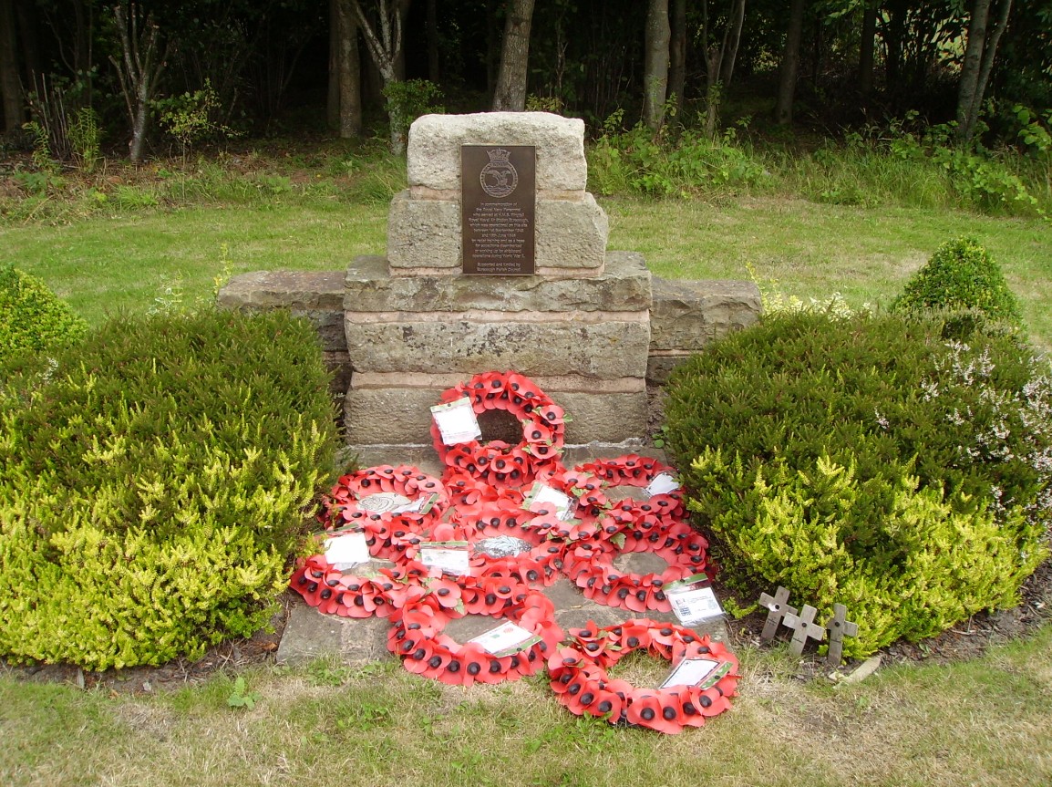
Ringtail Monument Relocation
The HMS Ringtail Monument that was built during 2004 has been relocated across the road to the new ringtail retail park.
 Photo Courtesy of Lawrence Critchley
but Photograph by Mike Dawson
The new monument and memorial garden have been
relocated outside of the new booths supermarket.
Photo Courtesy of Lawrence Critchley but Photograph by Mike Dawson
The bronze sculpture of the WW2 fleet air arm pilot is designed and built by Peter Hodgkinson
Photo Courtesy of Lawrence Critchley but Photograph by Mike Dawson
The supermarket itself has been designed to resemble a
WW2 aircrafthangar and stands on part of the airfield site
Inside Booths is this Display Area of H.M.S. Ringtail
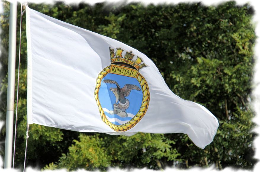
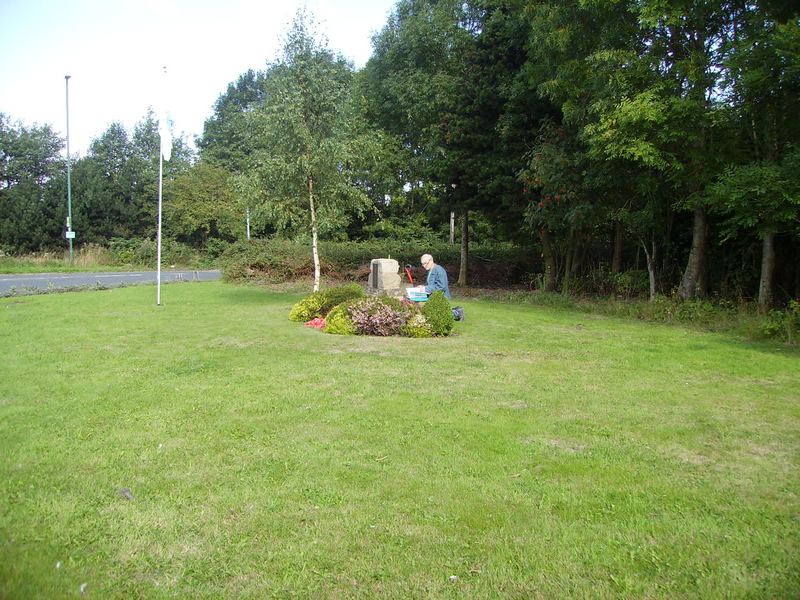
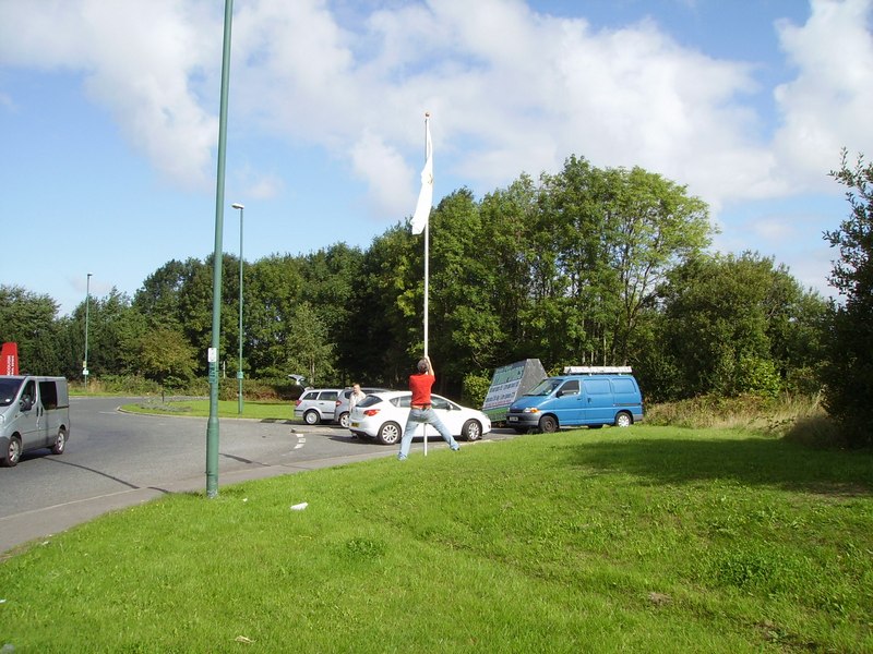
Lawrence Critchley Temporarily Putting up The Ringtail Flag
near the Monument For a Photo-Shoot by Mike Dawson.
The monument and the flag will eventually be moved to a new
permanent location near the new nearby 'Booth's' Supermarket.
(Note: The supermarket has been designed to look like a hangar)
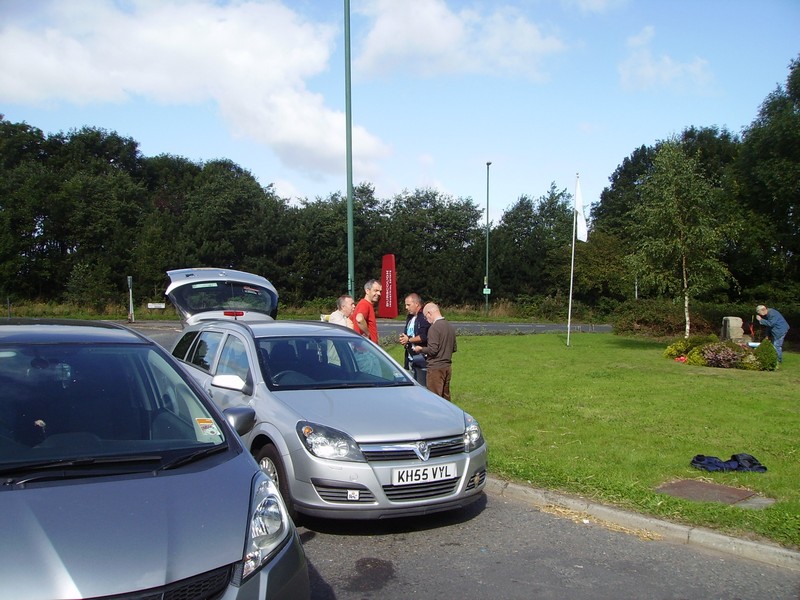
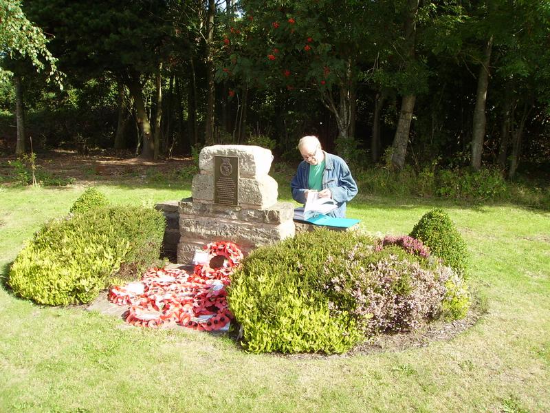
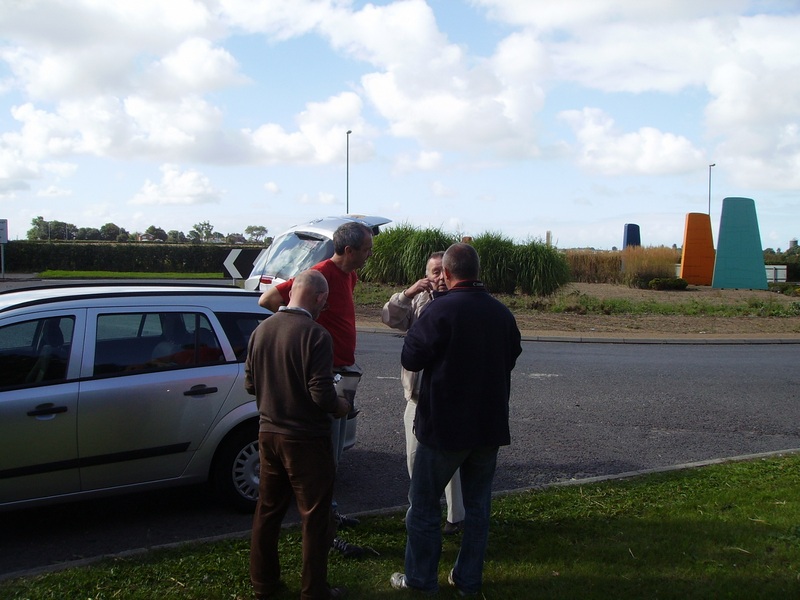
Lawrence Critchley (red shirt), Mike Dawson (blue jacket), Richard Houghton (brown jumper)
are dedicated to keeping the history of the airfield of HMS Ringtail 'alive'.
The 'guys' can be seen here talking to Brian Lea who was stationed at
HMS Ringtail/camp 2 for a short stay during his national service around 1955.
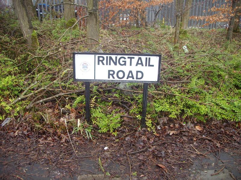
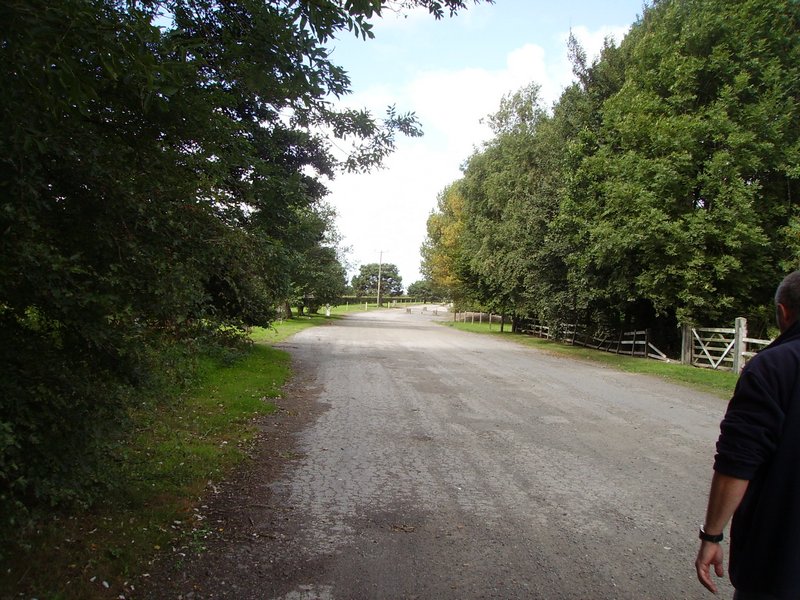
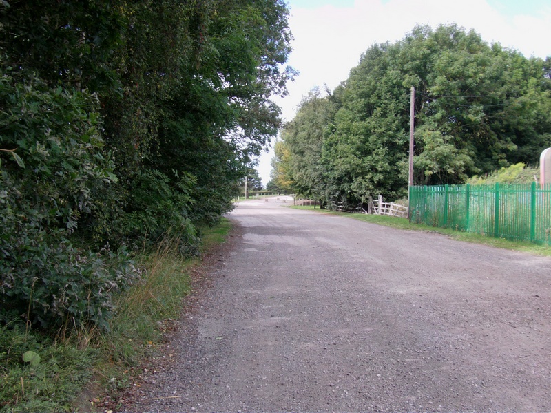
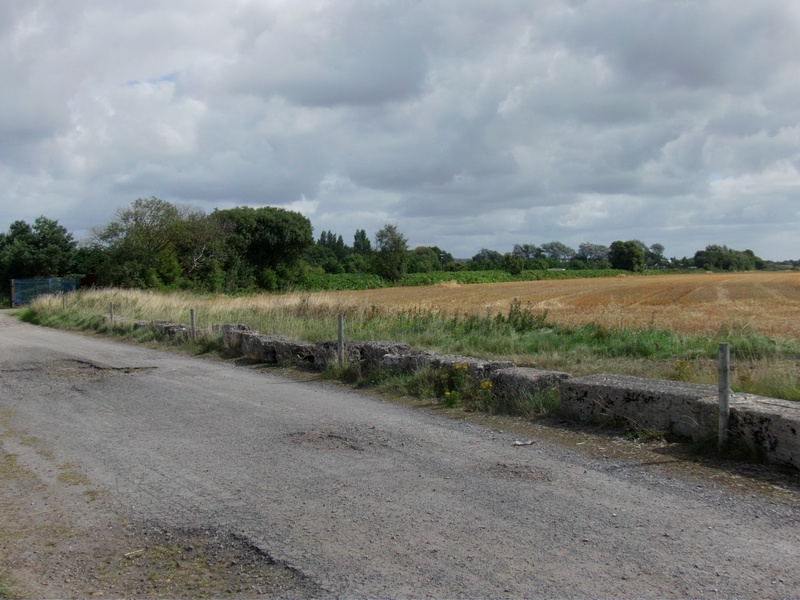
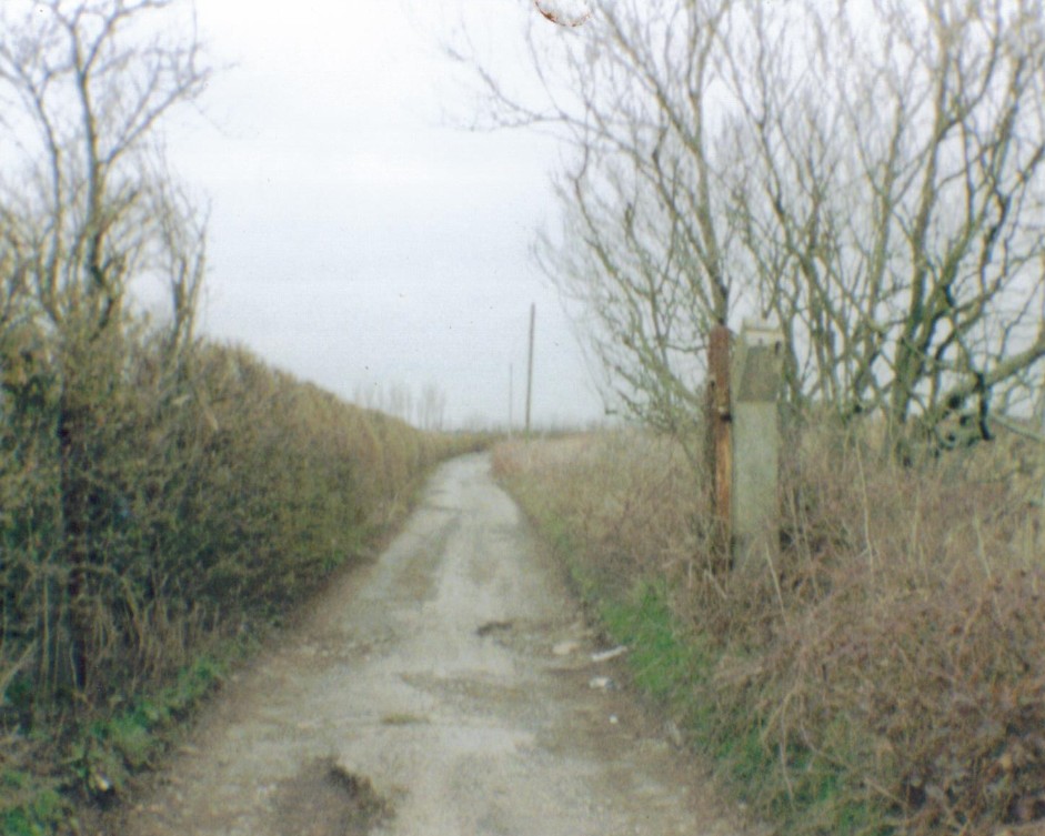
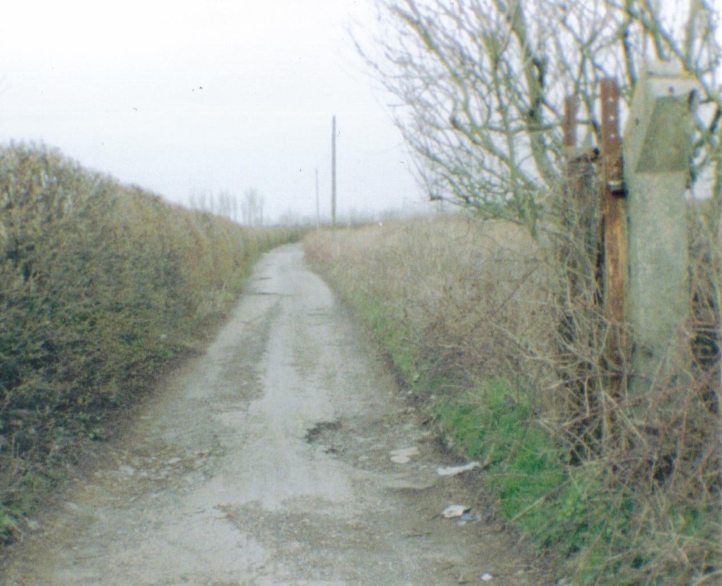
Ringtail Road
Keeping the History of the Airfield 'Alive' the Road has been Named 'Ringtail Road'.
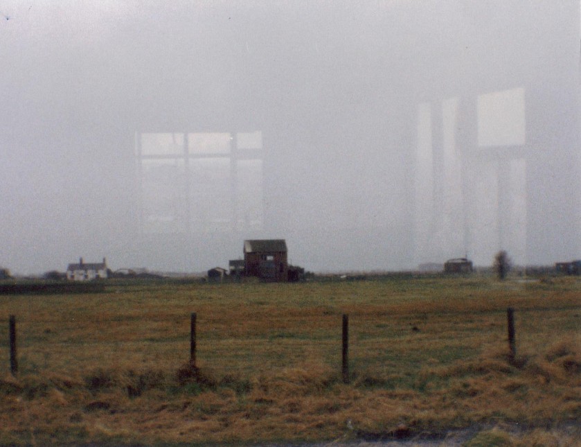
In the Distance (past the white barrier) is the 'Old' Remains of the North Perimeter Track Facing West
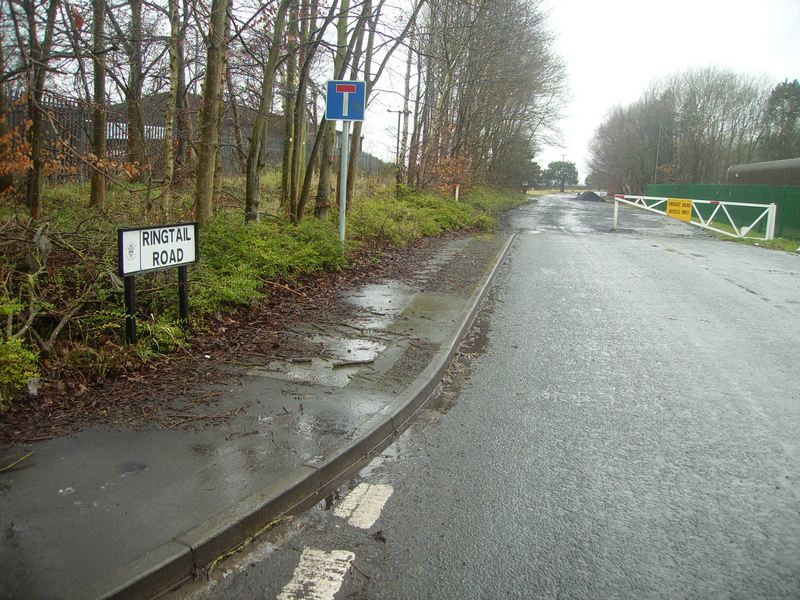
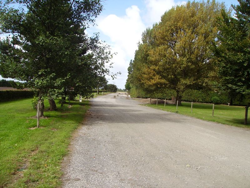
This photo is directly across the junction to the left of the photo above
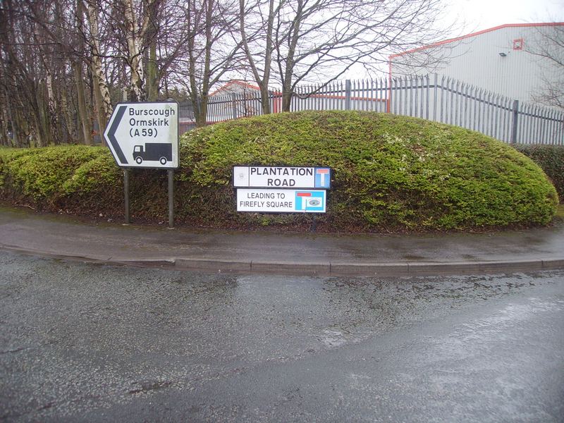
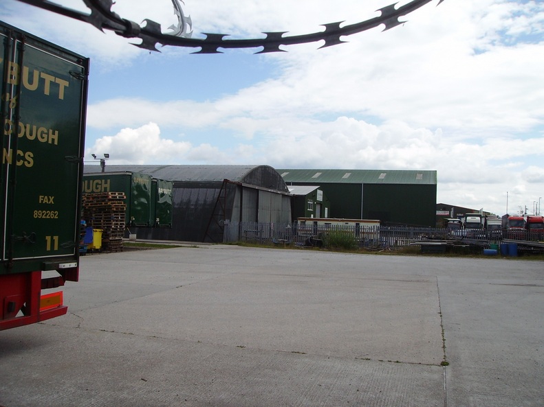
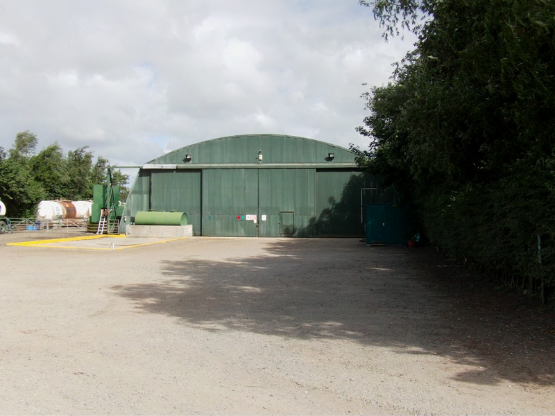
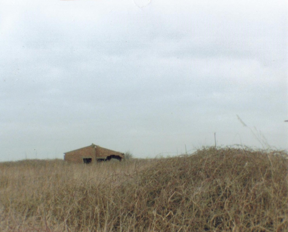
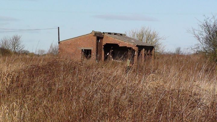
Admiralty 'S' Shed Close to the 'Plantation Road'
Sign Above Now Being Used by Baybutts Haulage
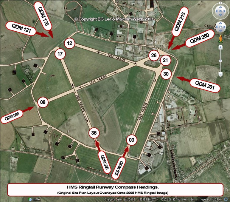
Airfield Record Site Plan
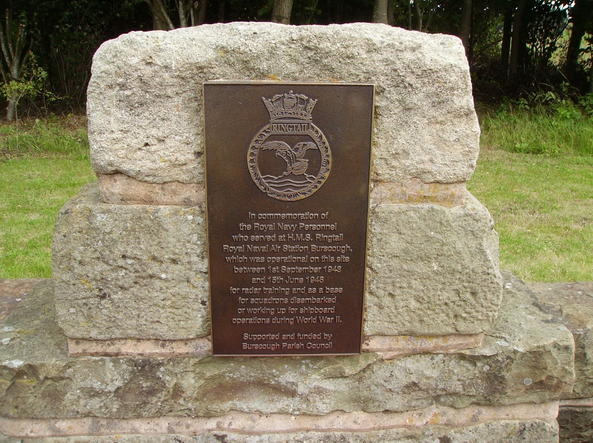
Burscough Airfield Royal Naval Air Station HMS Ringtail is 1 mile North East of Ormskirk in Lancashire.
The OS Reference is: SD425114
The Airfield Code is: -A4
The airfield opened on the 1st of September 1943 and closed in May 1946.
On the 15th of Jun 1946 the airfield was transferred to care and maintenance and on the 5th of May 1955 was transferred to the Admiralty Dockyards Department.
There were 4 runways to admiralty specification, i.e. 3 runways of 1,000 yards long by 30 yards wide & the 4th runway aligned with the prevailing wind of 1,240 yards long by 30 yards wide.
The runways were constructed of concrete and surfaced with tarmac.
The visual angle of approach at night was airfield lighting (Naval and RAF installed).
Living quarters were built on 2 camps ..... camp 1 off Higgins Lane and camp 2 off Abbey Lane to accommodate 189 officers, 1,204 chief petty officers and ratings, 15 women's Royal Naval Service Officer's and 355 women's Royal Naval Service Chief Petty Officer's and Ratings, and also, the Medical sick bay was in the station area on the east side of the airfield.
Airfield facilities consisted of:
Communications equipment was:
M/F and One Line M/F
H/F 4 T Lines H/F
Ground Radar Intermediate GCI
Homing Radio D/F
Beacons YG
Aircraft Radar Test Base Available
2 Wind Socks ... one on the west side of the landing area inside the taxi track and one at the intersection of the runways on the east side
4 Armouries to accommodate 4 squadron's
2 x 70 feet in diameter compass swinging bases
Meteorological office on the ground floor of the control tower
Machine gun and cannon test butts north of the landing area near the hangars
3 aircraft dispersal standings off the taxi track close to the control tower
Explosive area on the north west side of the airfield. Practice stocks for provision of 1 T.B.R & 4 F.R. Squadrons
8 Flood light standings
And 1 cloud height search light
Aviation fuel storage (holding 68,000 gallons)
Motor transport fuel storage (4,000 gallons)
Oil storage (4,000 gallons)
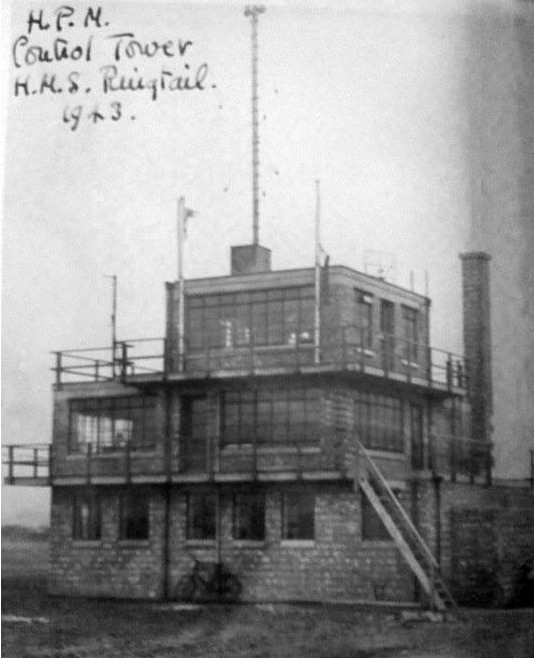
The Control Tower 1943
The control tower was situated on the east side of the landing area outside of the taxi way.
It had 3 stories with an internal stair case and the air watch office was on its roof (on the photo below the air watch office has been removed).
For reasons unknown the control tower was originally built with just 2 floors, and the air watch office was on top of the 2 floors below as you can see?
We think, that the control tower only had the earlier 2 floors because the airfield's had to be built so quickly (by McAlpine's)
Later, an additional 3rd floor was added to comply with the standard naval watch office design (drawing number 3860/42) as you can see in the image below.
The Ground Floor
The ground floor was offices for the meteorological section and consisted of 3 offices:
Met office
Senior Met Officers Office
Met Teleprinter Office
Also, ladies and gents toilets and store room.
A stair case descended down to a small basement which housed the central heating boiler and PBX telephone equipment.
The First Floor
The first floor consisted of 4 offices:
2 General Offices
1 Air Staff Officer Office
1 Commander of Flying Office
The offices were divided up with glass and wood partitions with message hatches and 2 doors opened out to the platform outside.
The Second Floor
The second floor was for flying control and consisted of 1 office. There was only 1 office (compared to the other offices) simply because the rest of the floor area consisted of just seating and desks.
The Roof
The roof of the control tower was accessed by a steel vertical ladder through a roof hatch and this lead to the Air Watch Office and also sited on the roof was the communications mast and lighting gantry.
For safety, hand rails were fitted around all the corners of the roof.
The ground to air signals square was immediately north of the control tower.
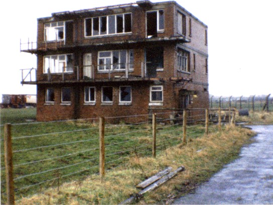
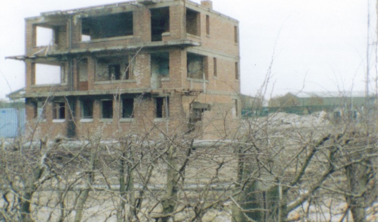
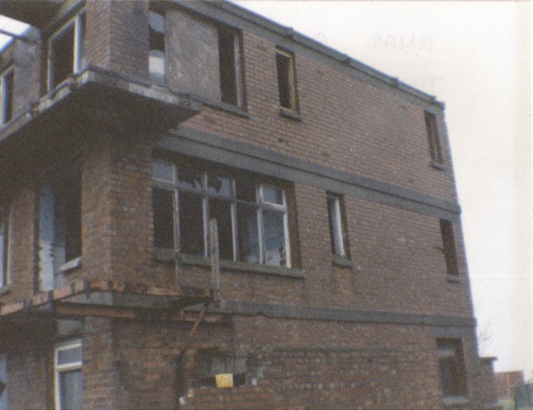
The Control Tower 1984
The hangars consisted of 32 admiralty 'S' type mainhill hangars (traverses size 60 by 70 feet and door height 17 feet and door width 55 feet) dispersed around the taxi track & were intended to store 6 - 8 aircraft with their wings folded.
18 of them were for the squadron with earth traverses, 14 of them were used for storage
Also 2 Callender Hamilton Hangar maintenance hangars (size 110 feet by 185 feet).
1 Callender Hangar was the ARS Workshops and the other Callender Hamilton Hangar was the reserve servicing workshops to 4 - 6 sqadron scale.
The size of the Callender Hamilton Hangars had a span (width) of 90 feet and 185 feet in length with a door height of 23 feet .... drawing number 3546/43.
Some hangars are in their original positions & others have been moved to other areas on the airfield.
The Air Station was used mainly by day and night fighters.
After the airfield closed in 1957 it was used by crop-spraying aircraft and by a parachute club.
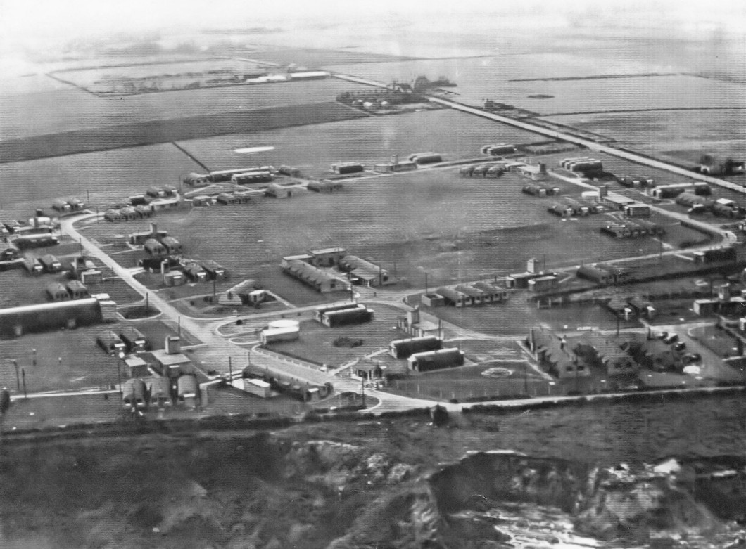
Camp II - Living Quarters 1945
1771 Squadron at HMS Ringtail, the
Squadron arrived on the 3rd March 1944 and
departed at the end of July 1944.
1820 Squadron at HMS Ringtail.
The Squadron arrived on the 11th of
August 1944 and was disbanded
in December 1944.
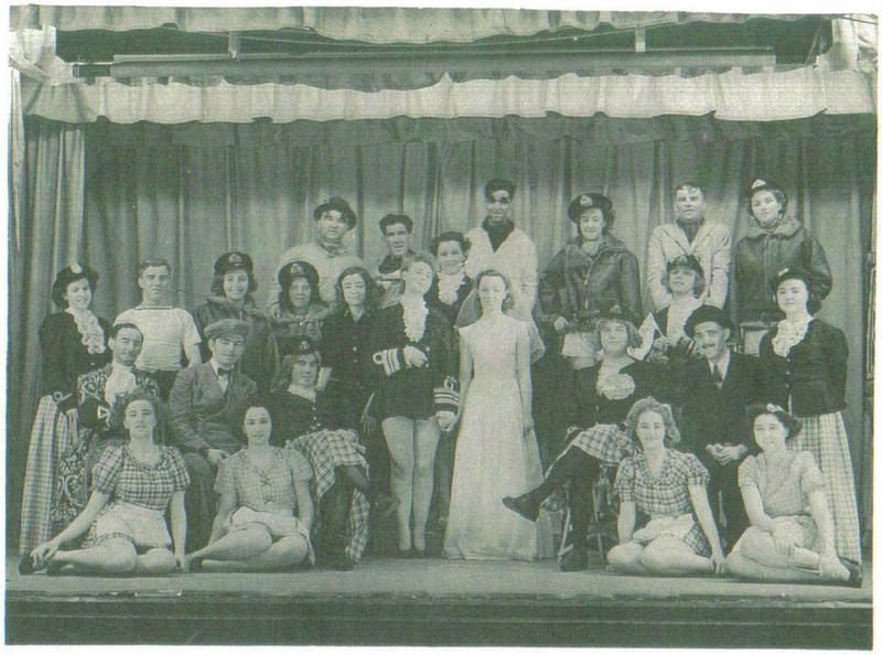
Christmas of 1944.
Panto of Cinderella.
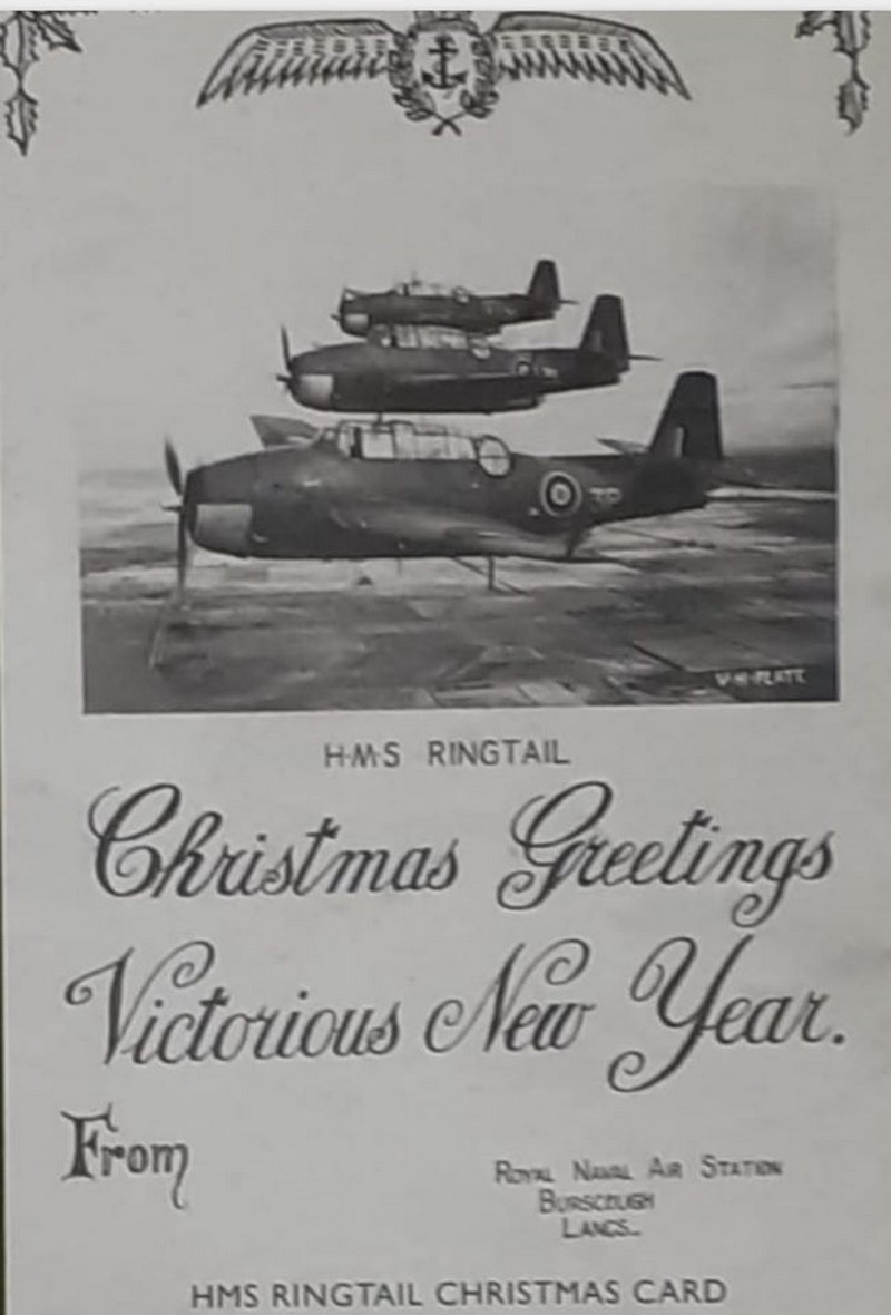
 Ringtail Xmas Card
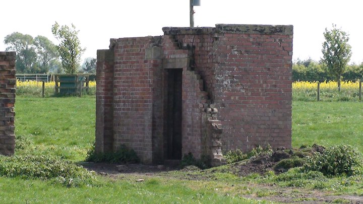
 Control Tower Photo Just Before Demolition ....
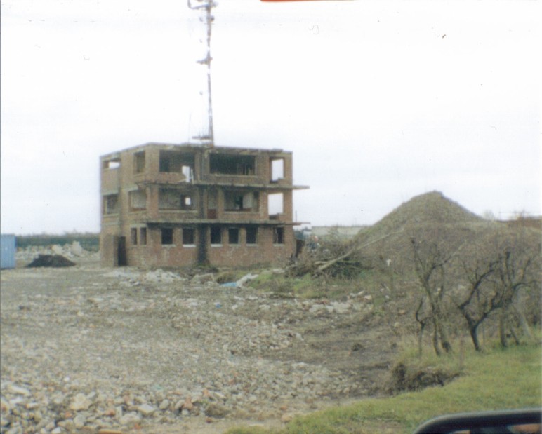
Control Tower Photo Just Before Demolition ....
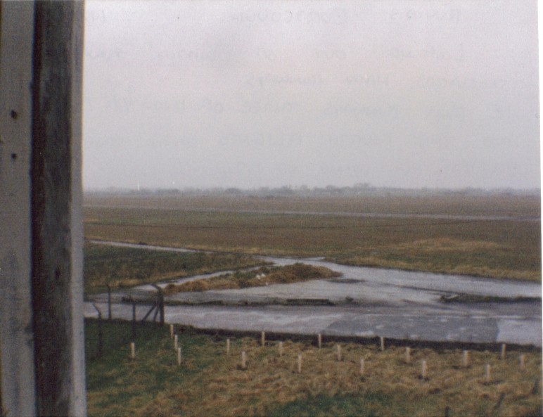
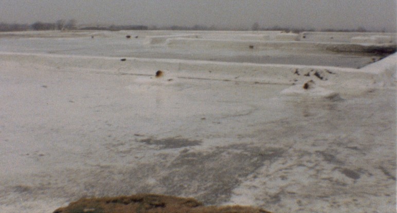
View of the Airfield From the 1st Floor
of The Control Tower 1984
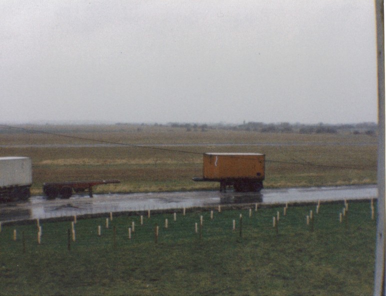
View of the Airfield From the 1st Floor
of The Control Tower 1984
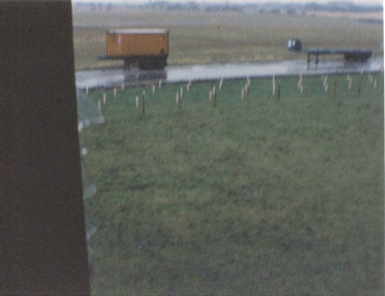
View of the Airfield From the 1st Floor
of The Control Tower 1984
The Roof of The Control Tower 1984
(The raised area shows the outline of the air watch office)
Side View of The Control Tower 1984
Crash Tender & Ambulance Shed 1984
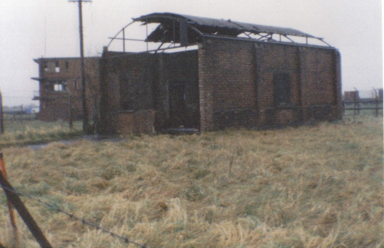
Free Gunnery Trainer & To The Right is
The Ambulance & Crash Tender Shed 1984
Aviation Fuel Pump House 1984
(The fuel tanks are below ground)
Explosives Area Plan
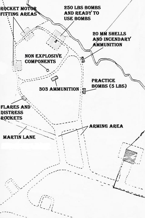
(ALL of the explosive area photographs below are courtesy of Michael Dawson Photography)
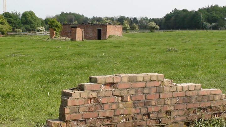
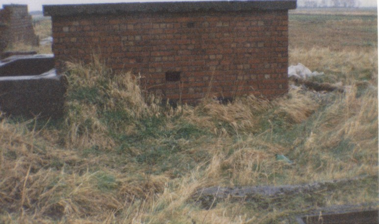
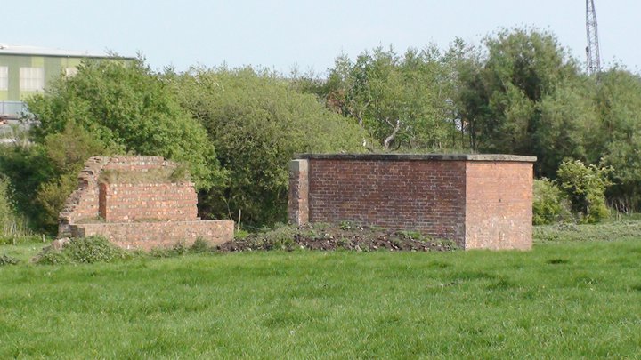
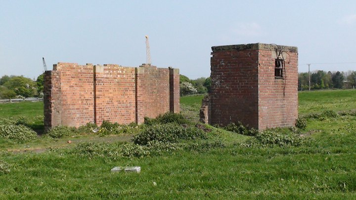
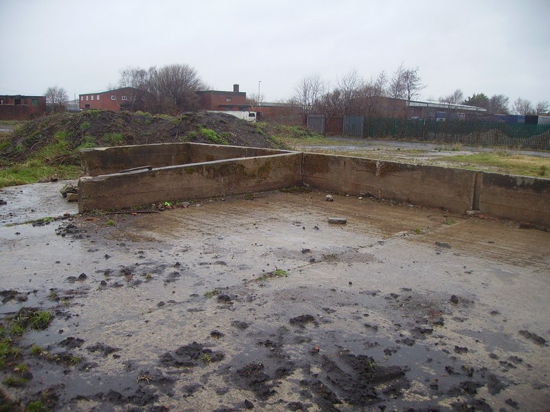
In the foreground are the remains of the rocket motor fitting area blast walls, and in the distance can be seen the remains of the non explosive components building (small) and 303 ammunition building (large), on the explosives area, 29th April 2011.
Remains the flares and distress rockets building on the explosives area, 29th April 2011.
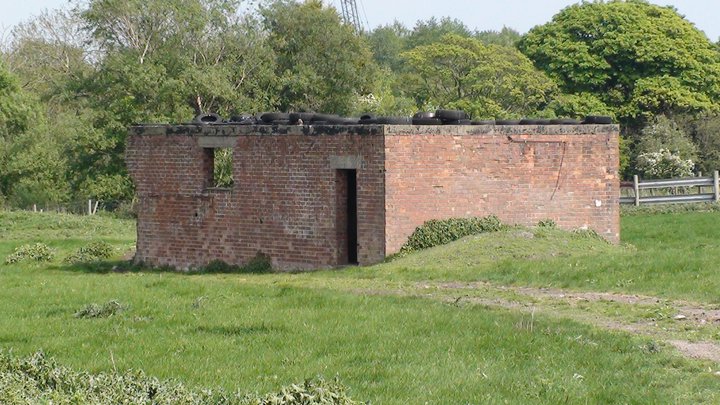
Remains of the 20mm shells and incendiary ammunition building on the explosives area, 29th April 2011.
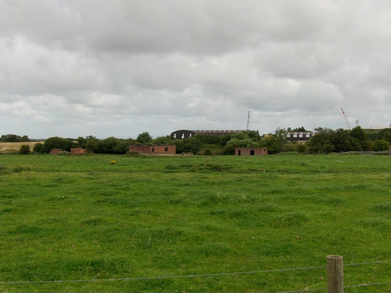
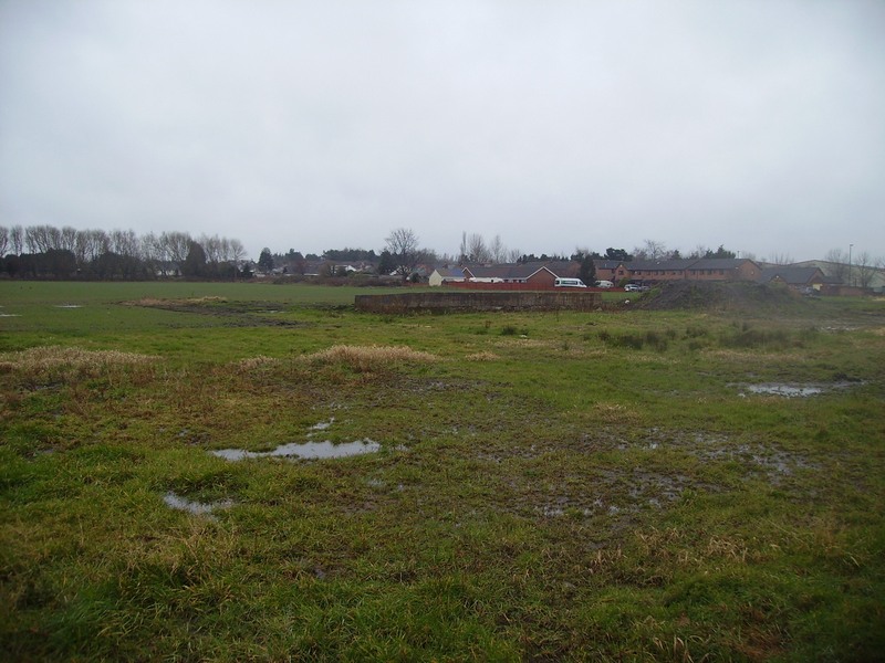
Remains of the 5lbs practice bombs building on the explosives area, with one of the original mainhill hangers in the distance, 29th April 2011.
Remains of the 20mm shells and incendiary ammunition building on the explosives area, 29th April 2011.
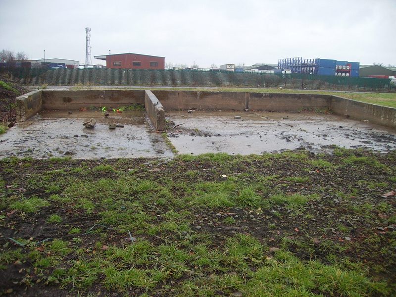
Remains of the blast wall (left) and the ready to use bombs / 250lbs
bombs building on the explosives area, 29th April 2011.
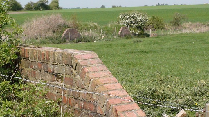
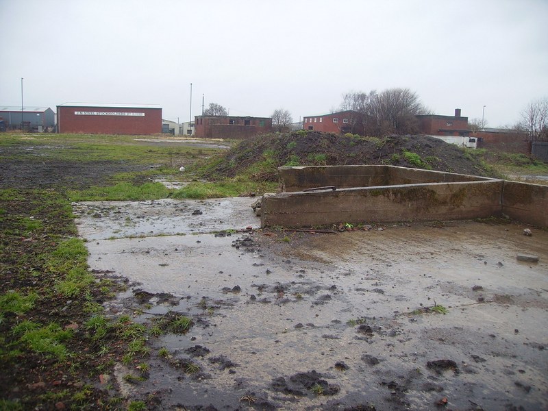
Remains of the blast walls on the rocket motor fitting area, on the explosives area, 29th April 2011.
Remains of the flares and distress rockets building (left), 303 ammunition building (centre) and the 20mm shells and incendiary ammunition building (right), on the explosives area, 29th April 2011.
Remains of the 303 ammunition building on the explosives area, 29th April 2011.
Remains the flares and distress rockets building on the explosives area, 29th April 2011.
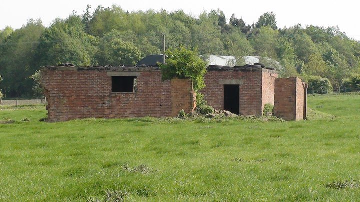
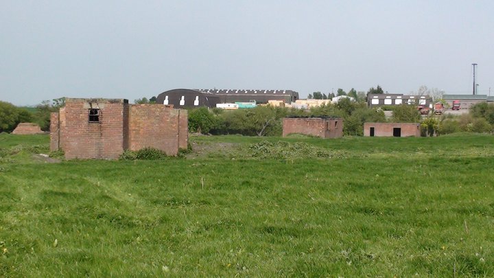
Remains of the non explosives components building (front) and the 303 ammunition building, on the explosives area, in the background can be seen one of the old mainhill hangars, 29th April 2011.
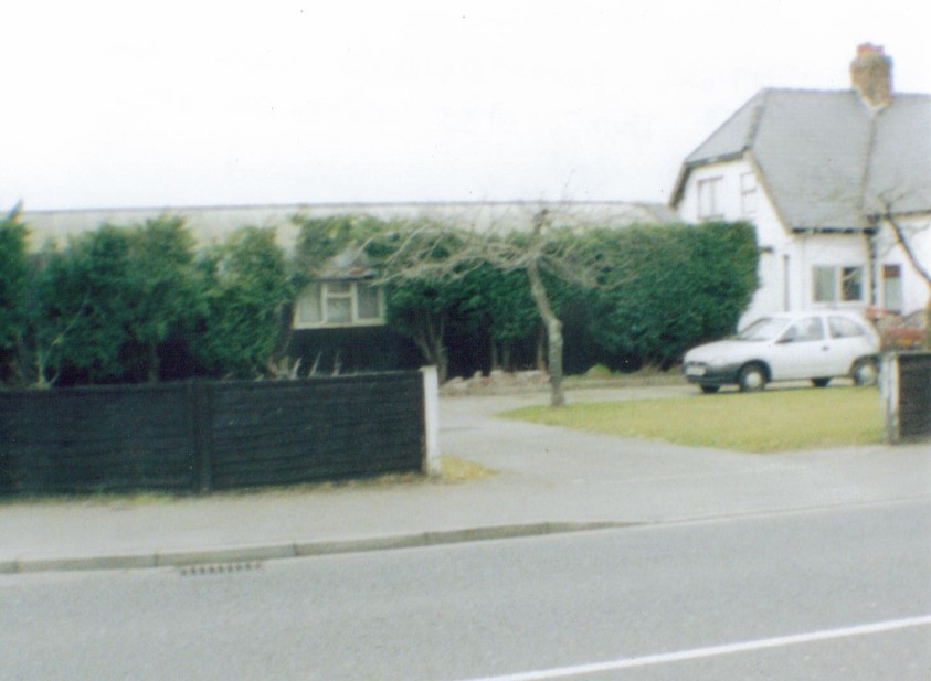
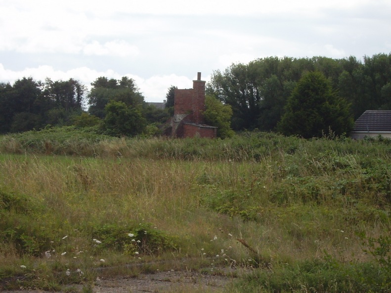
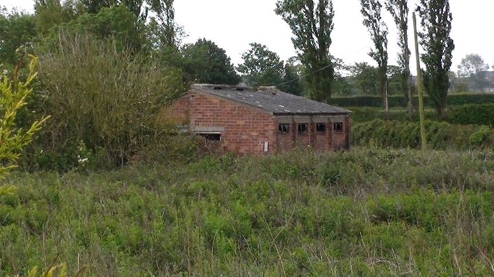
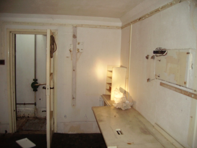
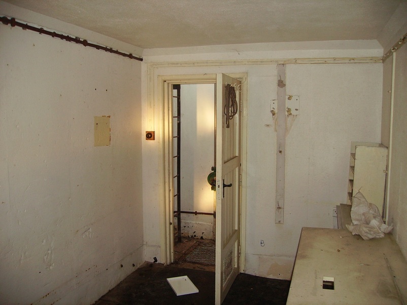
The Station Commander of HMS Ringtail's House Called The Retreat (Date of Photo 2003)
To the right of the photo is where the admiral of the camp lived and was called 'the retreat' and it was opposite the parachute packing house and the sub station. On the left of the photo is a nissen hut and was used as offices for the camp and later after WW2 it was used as a canteen for the civilian work force that worked on the airfield in the maintenance workshops.
Built 1935 and demolished the 5th of February 2013
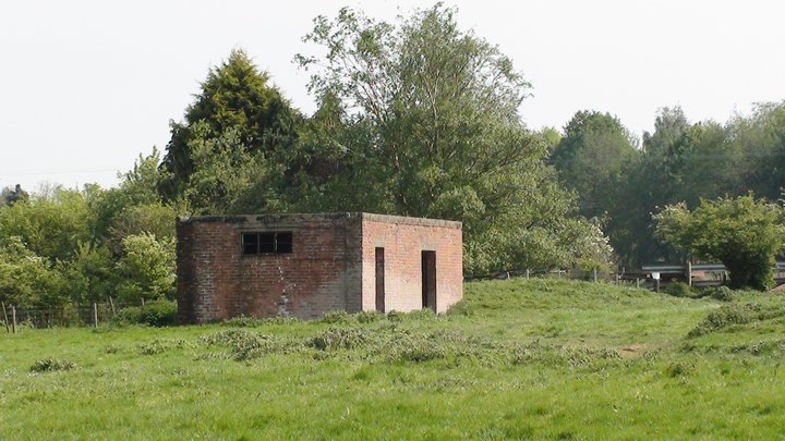
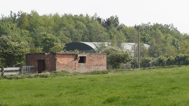
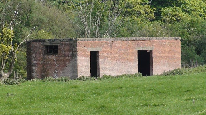
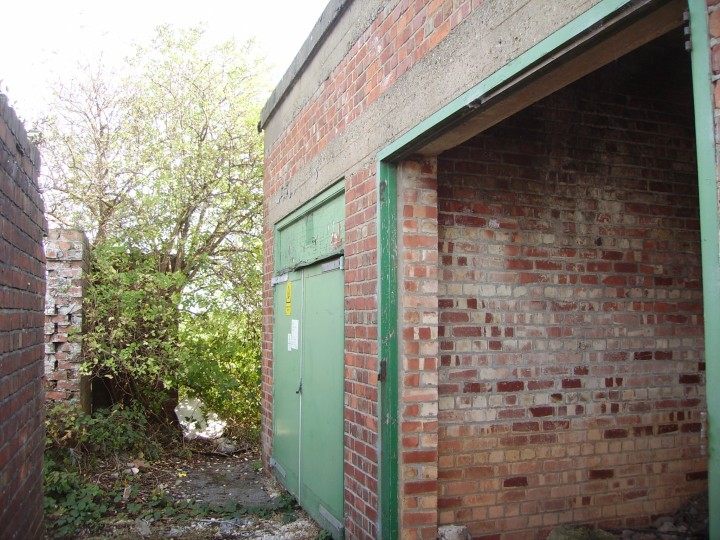
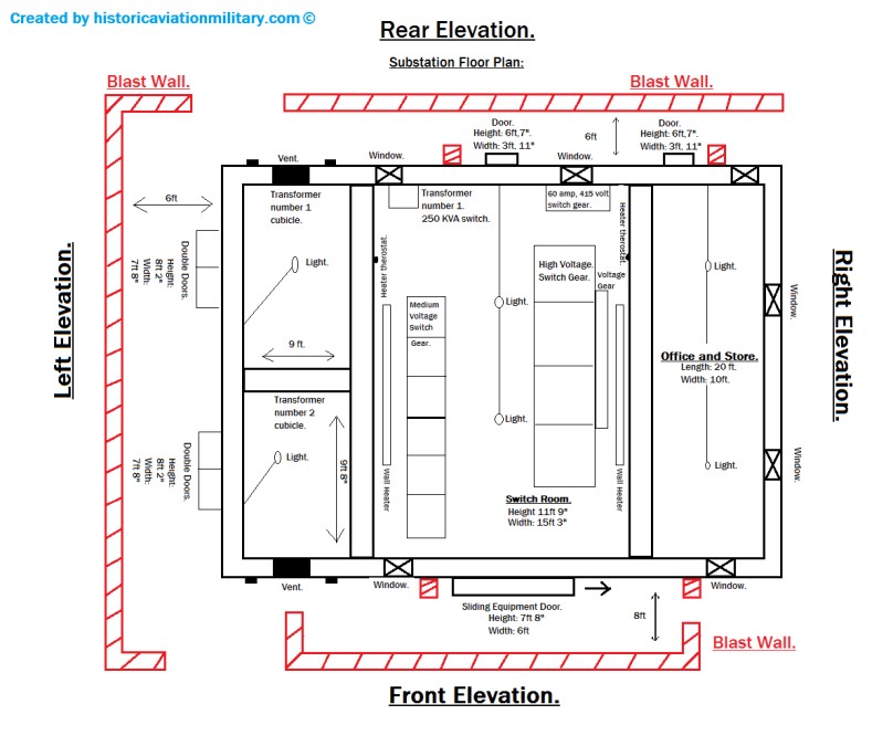
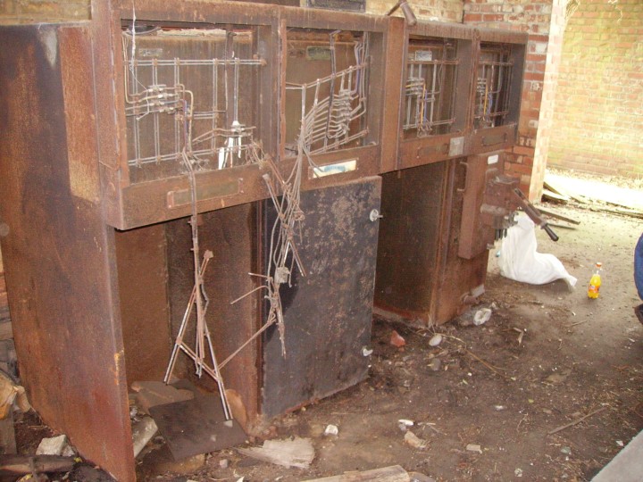
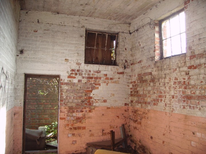
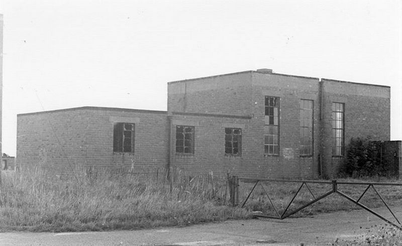
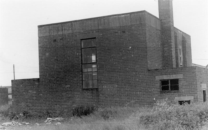
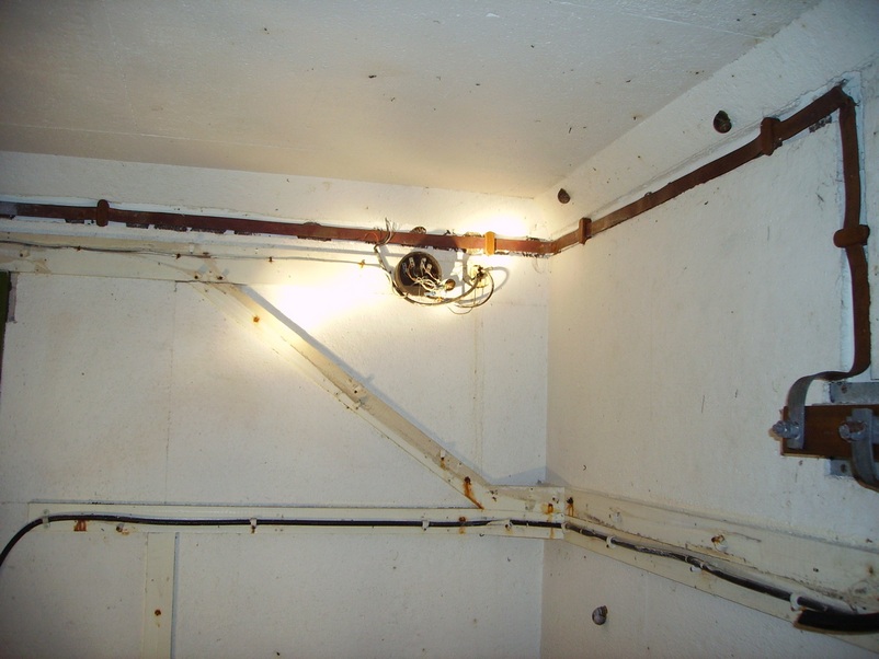
Sub Station Main Electrical Distribution
Centre Building 201 Camp III
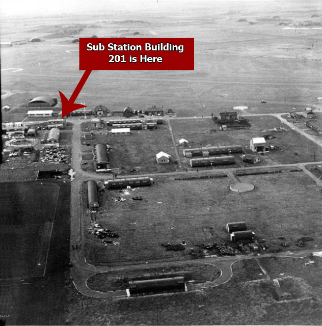
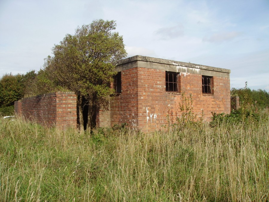
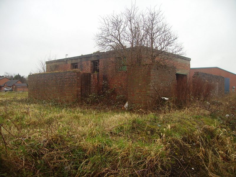
The sub station is split into 3 sections.
The main switch room is in the centre of the building and is 20 ft long x 15 ft 3 inches wide, with a front right sliding equipment door and the opening size is 6 ft wide x 7 ft 8 inches high, and the rear exit door is 6 ft 7 inches x 2 ft 11 inches.
Background heating was provided by 2 electrical wall heaters controlled by room stats.
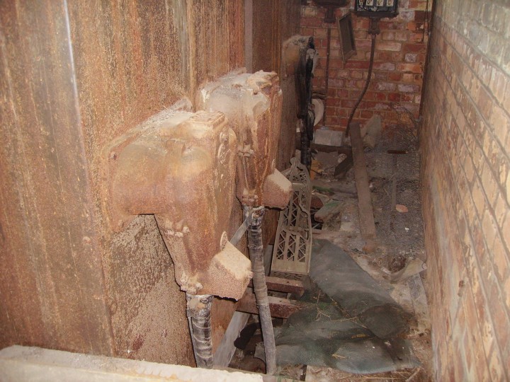
The left side of the building has 2 transformer cubicles 1 and 2.
Both cubicles are 9 ft high x 9 ft 8 inches wide, with double doors and the opening size of both doors is 8 ft 2 inches high x 7 ft 10 inches wide, with 1 high level air vent and 2 low level small vents in each cubicle housing a transformer of 10,000 volts high voltage with secondary output of 3,000 volts medium voltage.
The right side of the building is an office and store and is 20 ft long by 10 ft wide, with a rear opening that is 6 ft 7 inches high by 2 ft 11 inches wide.
Inside height of all rooms is 11 ft 9 inches.
High level windows in switch room and store room for natural light.
The building is built of 13 and a half inches of solid brick walls supporting the reinforced concrete flat roof.
A heavily protected brick blast wall 13 and a half inches thick and 8 ft 6 inches high.
It runs full length of 3 sides of the building where door entrances are present.
All cabling between switch room and transformer cubicles are run in the solid concrete floor ducts with removable slab covers.
All cables are lead sheathed steel tape.
All cables entering and leaving the building are run in clay pipe cable ducting.
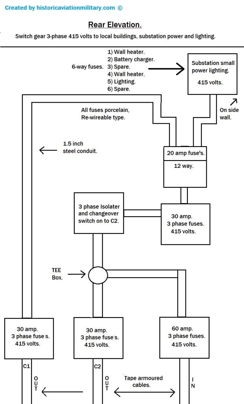
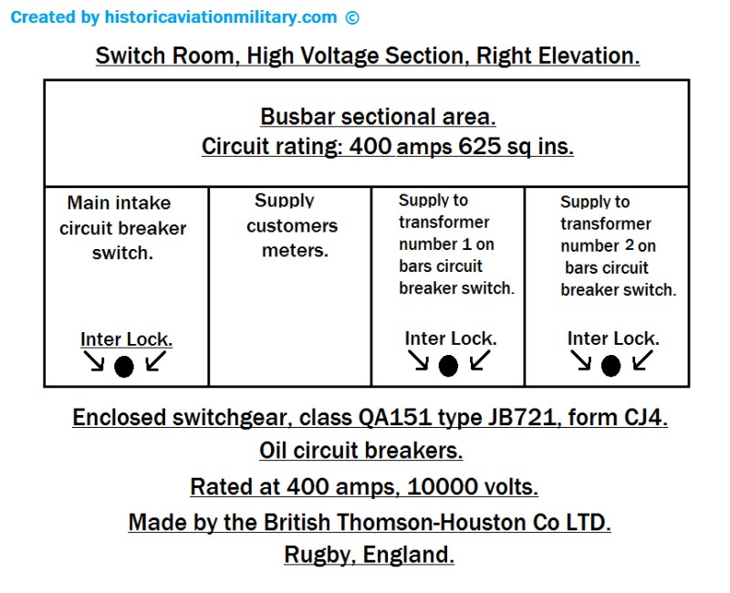
The sub station switch gear is 10,000 volts primary with high voltage oil circuit breakers enclosed class QA151 type JB721.
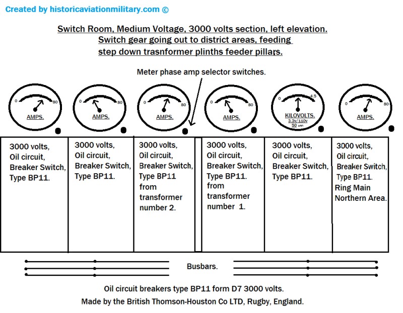
Secondary voltage is 3,000 volts medium voltage, with oil circuit breakers type BP11 that are supplying ring mains that go out to outdoor district area transformer plinth secondary sub station feeder pillars in to useable 415 volts 3-phase supplies.
All switch gear is made by the British Thomson Houston Co Ltd Rugby England.
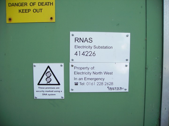
Note the voltages medium and high are different to the ones used currently.
Electricity North West are still using transformer number 1 cubicle which is still referred to as electricity sub station 414226 R.N.A.S. (Royal Naval Air Station)
Transformer Cubicles Number 2 in the Foreground & Number 1 in the background
Switch Gear 3-Phase 415 Volts (Rear Elevation)
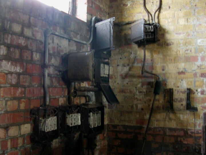
Switch Room High Voltage Switch Gear (Right Elevation)
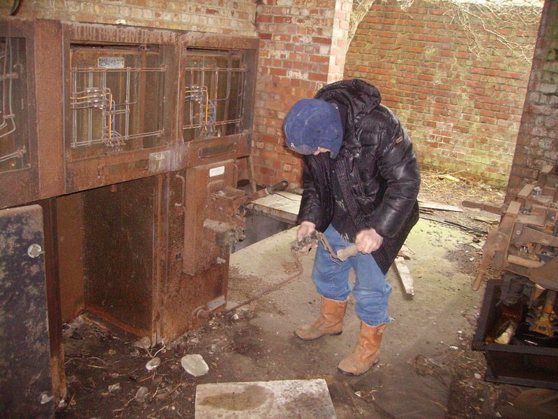
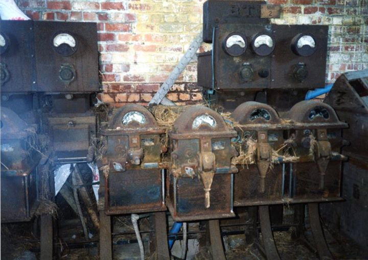
The Photo Below Was Taken in 2013
The dangling cables (as shown on the photo above) were attached to
metering equipment (as shown on the photo below)
Please note: The actual busbars are situated behind the top 4 enclosures.
Malc Recently Found the 10,000 Volt Switchgear Interlock
Handle Hidden under Rubbish (2015 Update Photo)
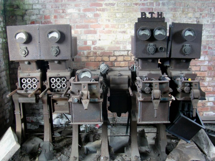
The 2004 Image Below Shows The
Original Switchgear Almost Complete
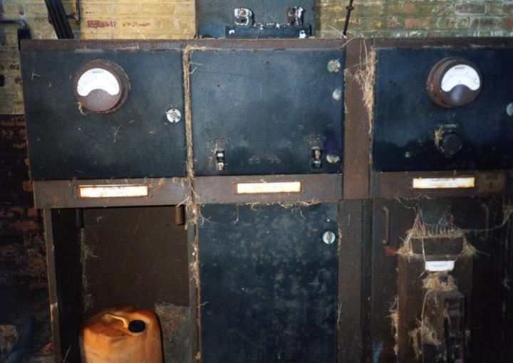
Image Below (Taken 2013) Shows The Rear of the High Voltage Switchgear,
Showing the High Voltage Cabling
Left to Right: Transformer No.2 Supply, Transformer No. 1
Supply and main intake supply cable
Medium Voltage Switchgear & Metering (Left Elevation)
The Photo Below Was Taken in 2013
The 2004 Image Below Shows The
Original Switchgear Almost Complete
Medium Voltage Electrical Drawing
Showing The Sub Station 201
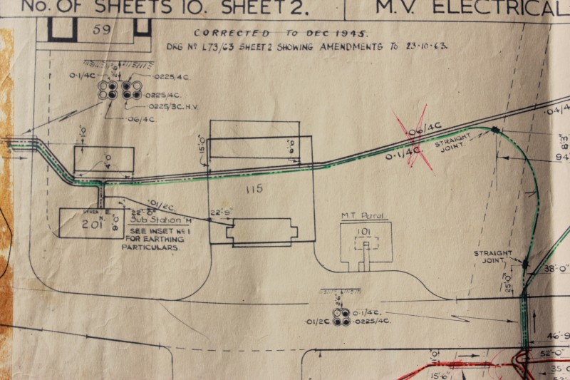
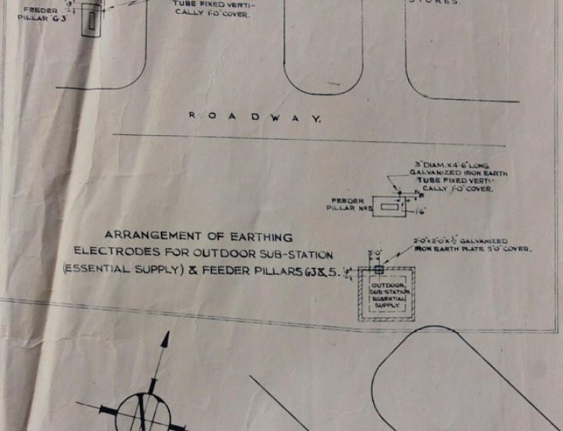
Earthing Drawing
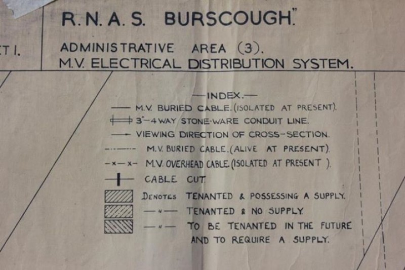
Medium Voltage Electrical Distribution System Legend
Sub Station Office and Store image Date Taken 2013
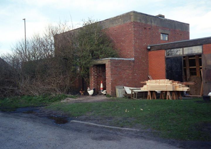
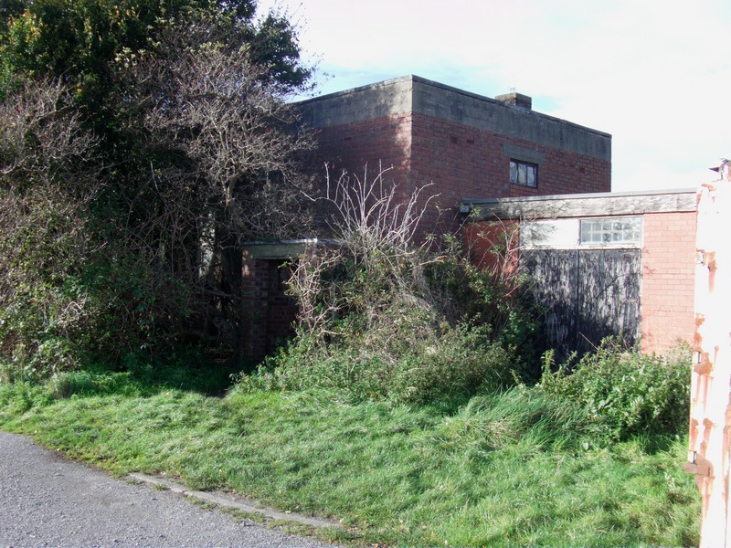
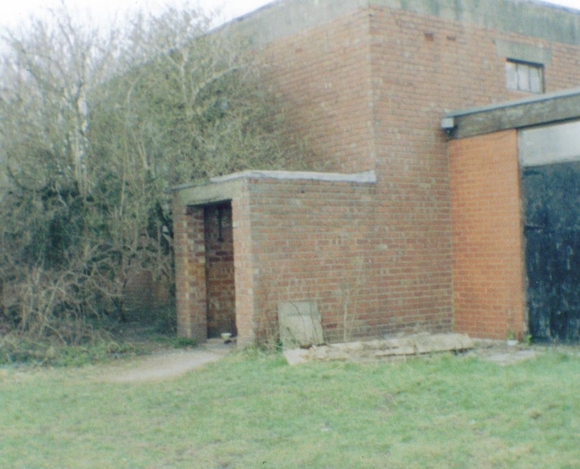
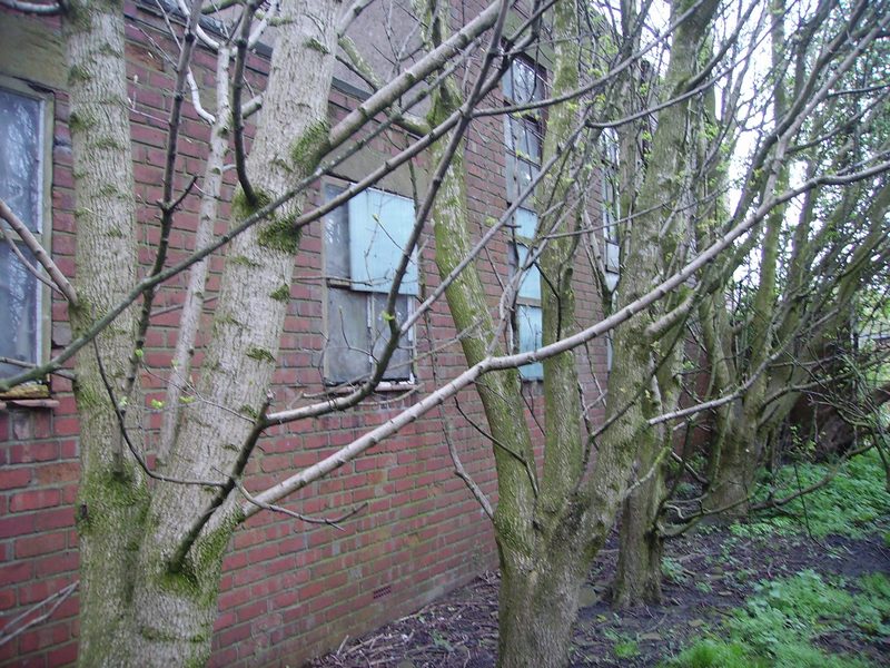
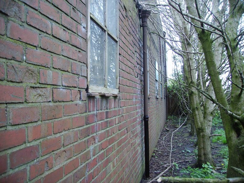
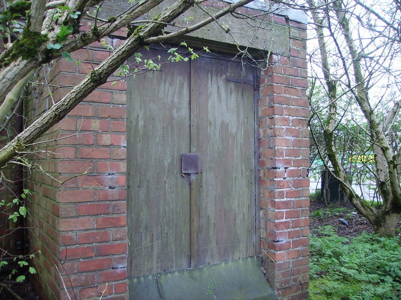
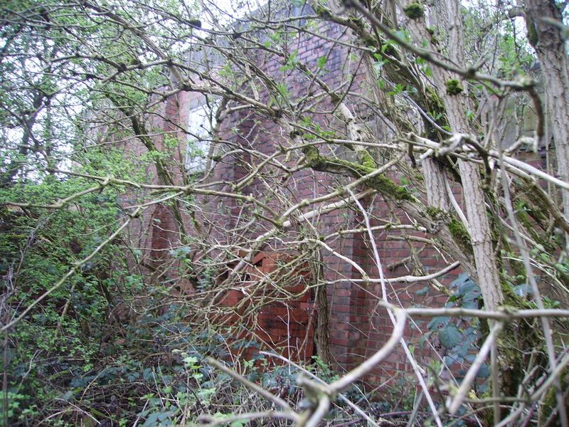
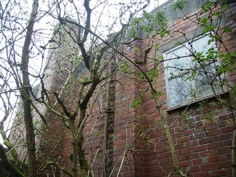
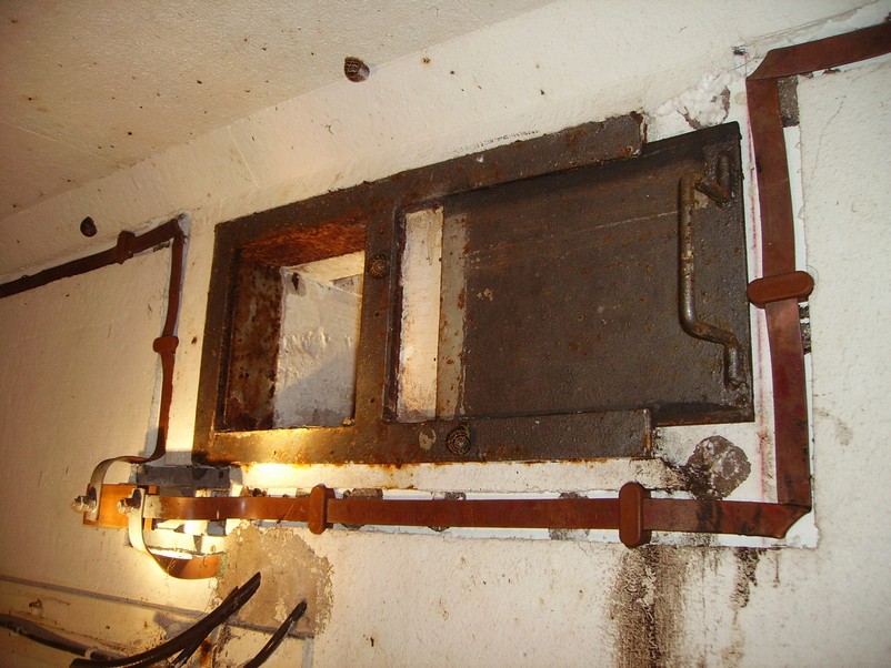
Parachute Packing House & Store Building 104
The parachute packing house & store is situated at the side of the sub station building (on camp 3) opposite what was the admirals house (called 'the retreat') and is where the parachutes were hung and dried and then re-packed ready for use again and carefully maintained.
The store had suitable housing that was adequately heated, lighted and ventilated for drying and airing the parachutes.
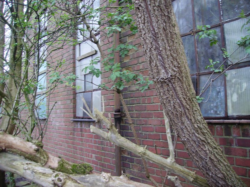
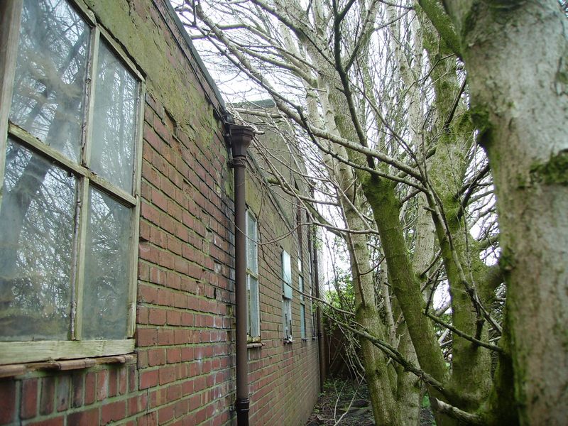
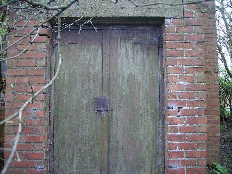
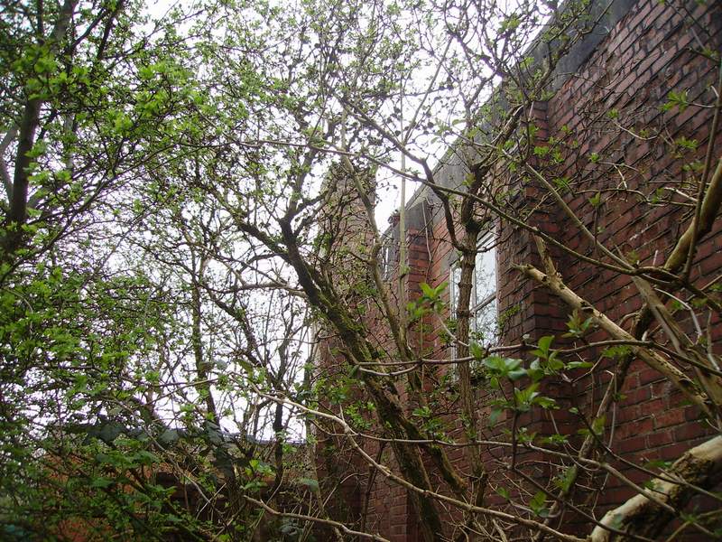
The tall part of the building with the 3 tall windows (known as the 'loft' and shown below) had a long flat table underneath that was used to help packing and had a pulley system at high level where the parachutes were hung to dry before they were packed again.
The 3 tall South facing windows (shown below in the photo) were for good natural light and is the actual front of the building. The lower building on the left is the parachute store and the taller part on the right is the parachute packing room.
The building was built of brick in stretcher bond with 2 reinforced concrete roofs for added protection.
(B&W photos below taken in the 1970's)
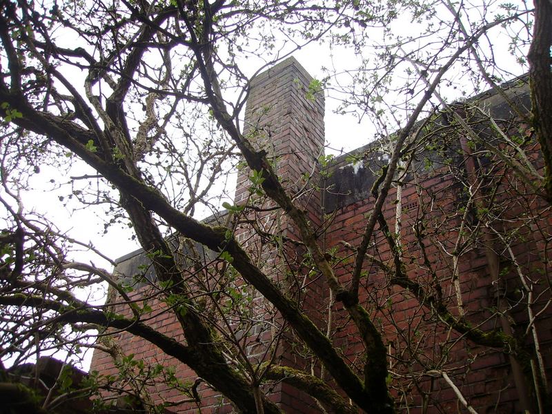
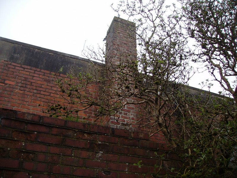
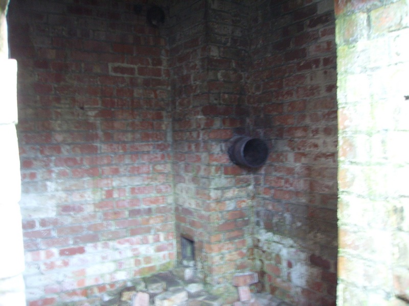
The right hand side of the parachute packing store shows the boiler house on the right of the photo below. The fuel and ash hatch can be seen just below the window to the right of the photo. The boiler chimney can also be seen.
The photo above was taken in the 1970's and as you can see below in the 2001 colour photo (taken at a slightly different angle) a modern building has been added to it.
You can still see the large window but it has been reduced in height. The main entrance in the black and white photo is on the left and on the colour photo it is where the chickens are roaming.
This was my own photo taken in 2003
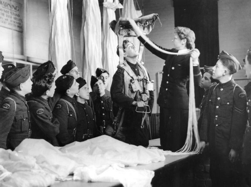
Air Cadet's at Ringtail on the 9th of February 1945 in the parachute packing house ... a WREN Officer shows trainee's the working's of a parachute.
(Please note: IWM - Used under the IWM's non commercial licence)
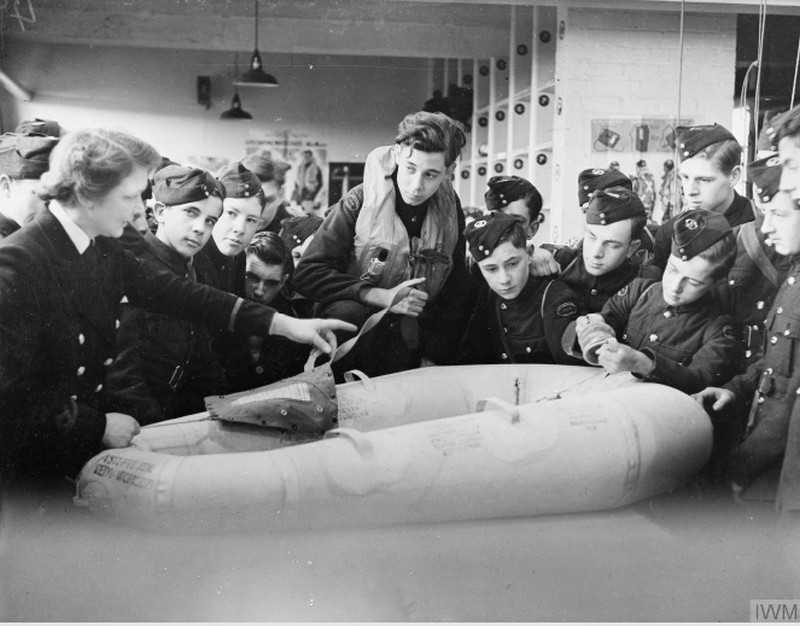
A Cadet is topping up an observer-type Dinghy while a wren officer explains its contents.
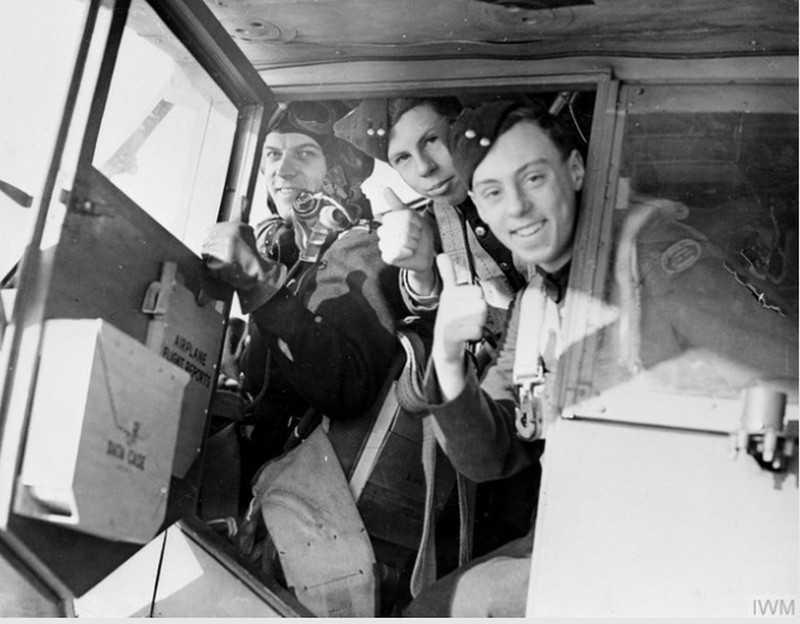
All set to go, the highlight of the cadet's visit to the station.
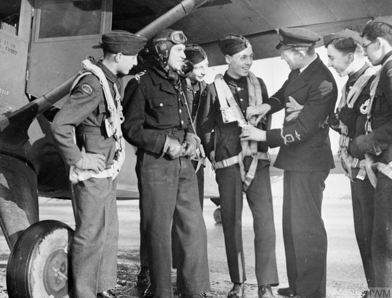
A fleet Air Arm officer explains the fitting of the parachute harness to ATC cadets while the pilot looks on.
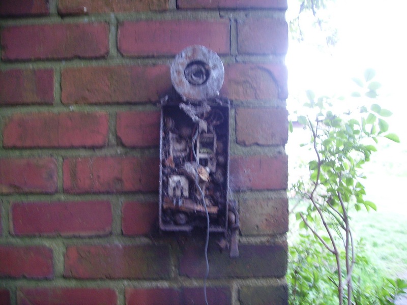
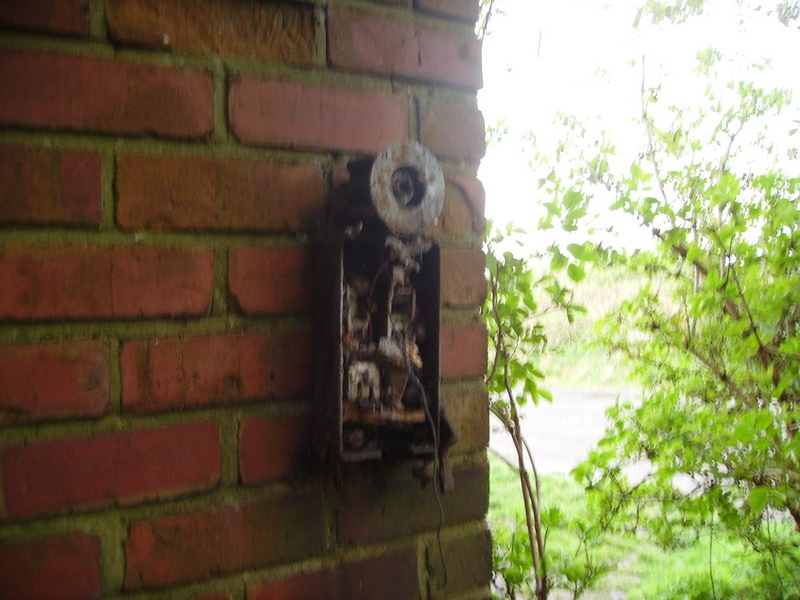
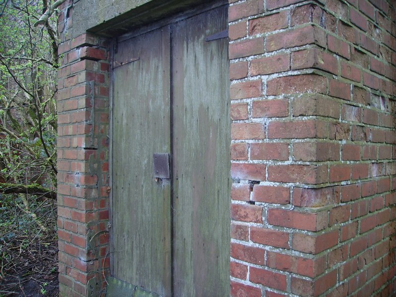
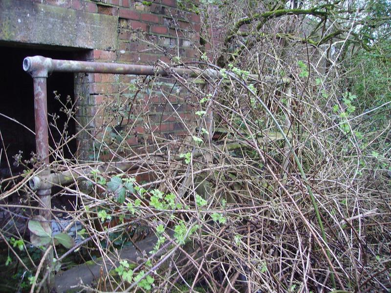
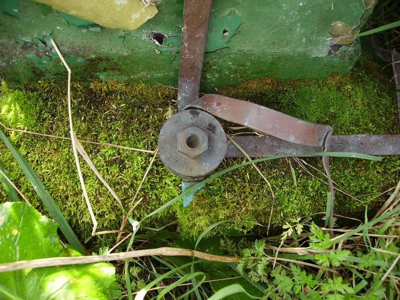
The front entrance shows an electrical cast iron switched fuse that looks like a light above it. It's purpose unknown?
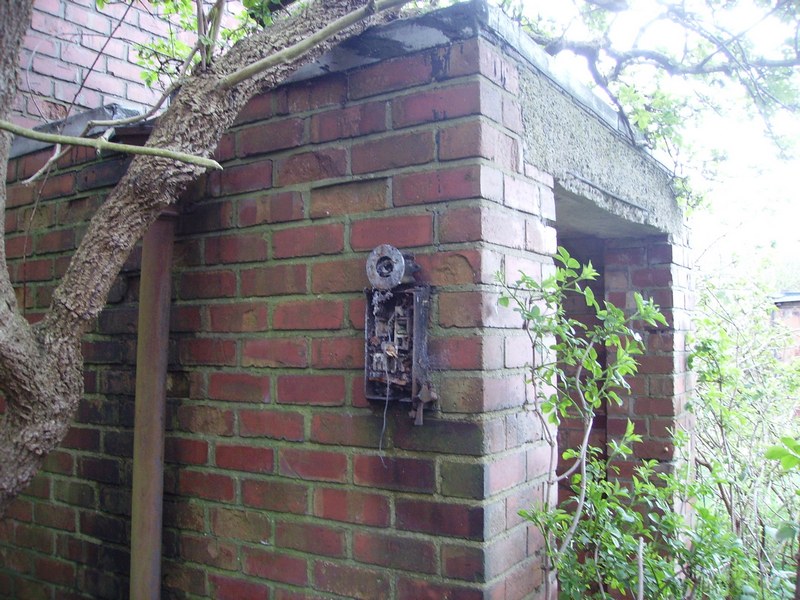
The front entrance view at a slightly different angle showing the back entry conduit that comes from the electrical switched fuse (above).
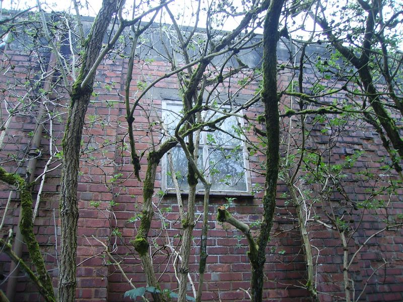
The front of the parachute packing house showing the 3 large windows.
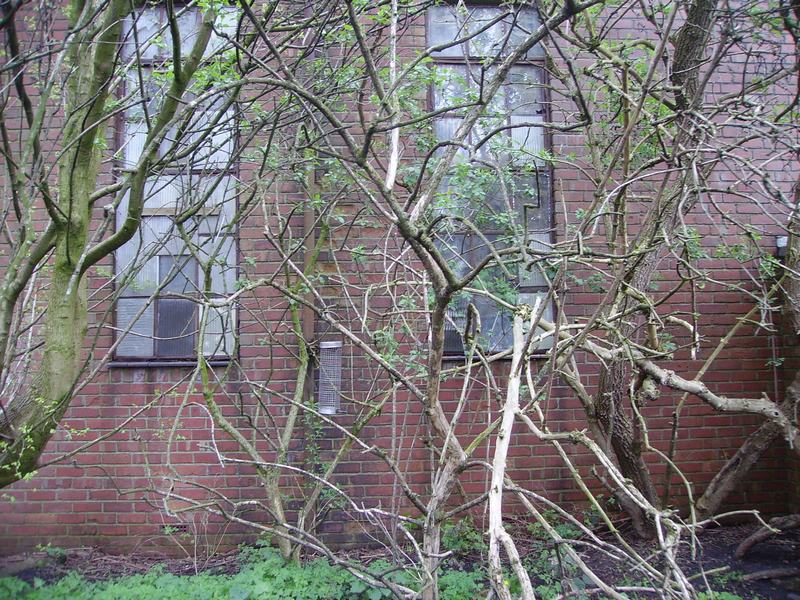
Front of the building with the packing room on the right and the parachute packing house store on the left.
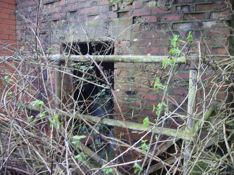
The rear door out of the lower buildings store room.
The back of the parachute packing room.
The boiler house chimney on the back of the parachute packing room.
Inside the boiler house showing the chimney flu.
Steps down to the boiler room. The boiler room is semi sunken compared to the parachute building in general.
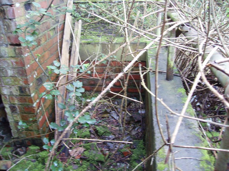
The boiler house stairwell guard rail.

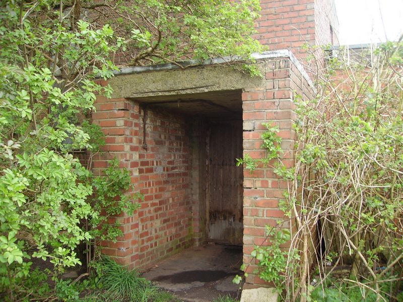
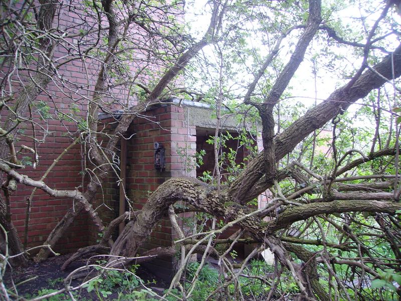
The front entrance.
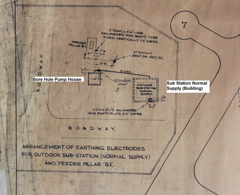
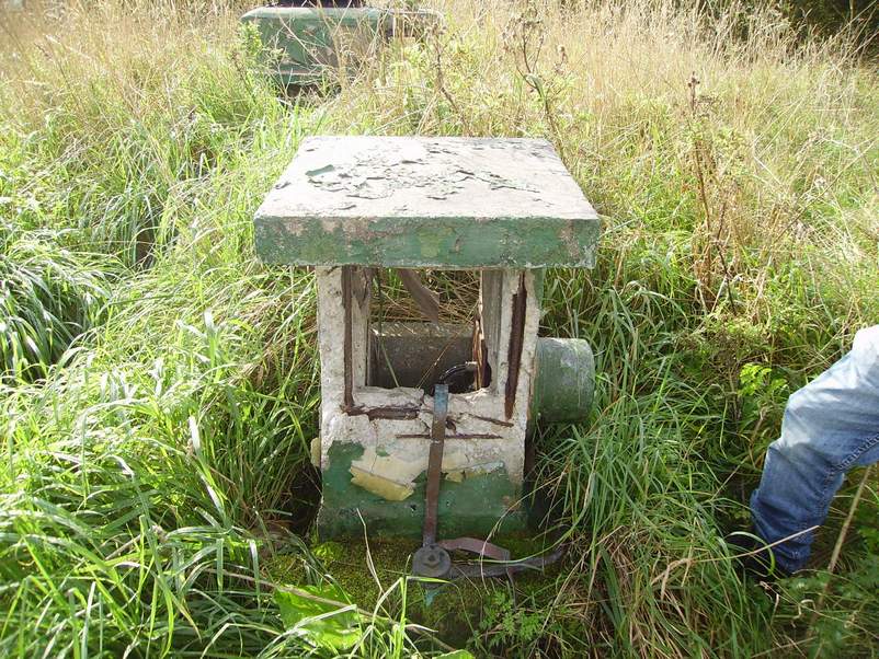
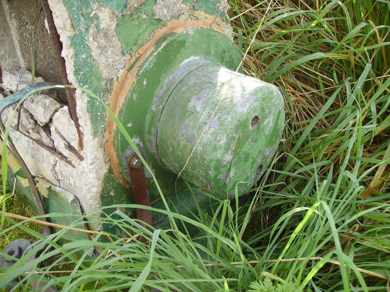
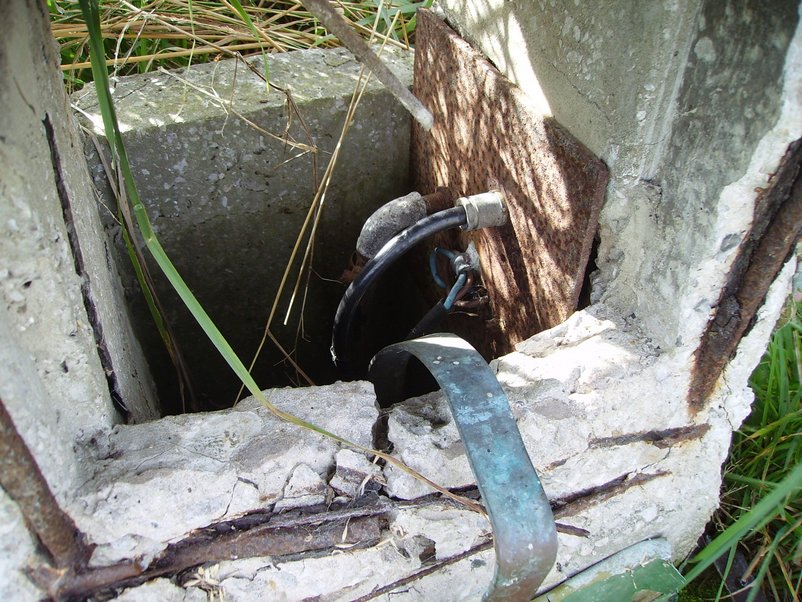
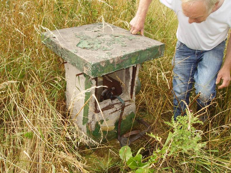
Bore Hole Pump House 2004 on Camp 3
(This is behind the parachute packing house)
Bore Hole Pump House 2014 on Camp 3
(This is behind the parachute packing house)
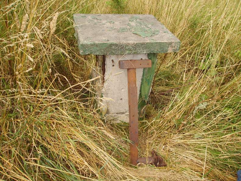
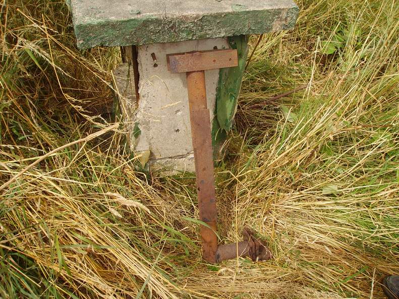
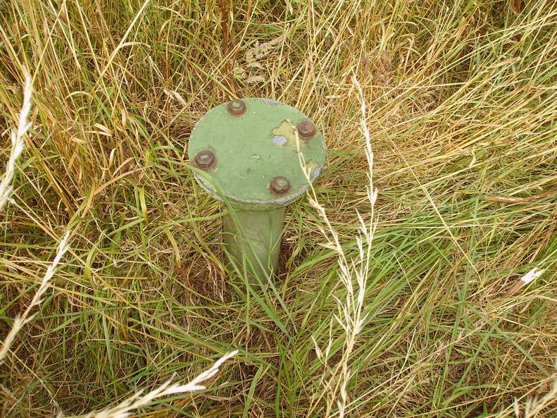
Electrical Plynth - Normal Supply 2014
(This is behind the bore hole pump house on camp 3)
Electrical Drawing of The Sub Station Normal Supply Building 0.1/4C
(3 Phase & Neutral) Supply Feeding The Bore Hole Pump House.
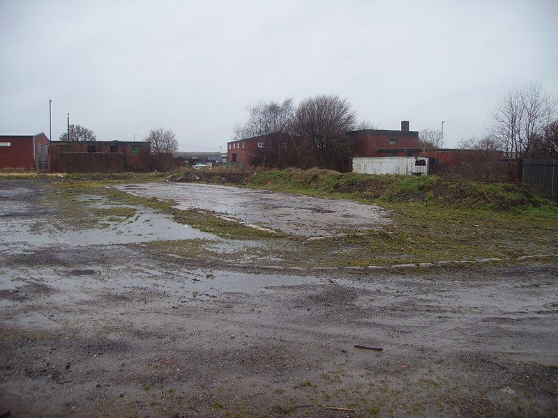
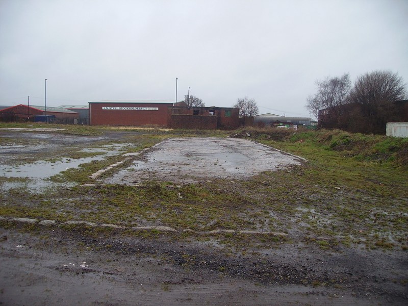
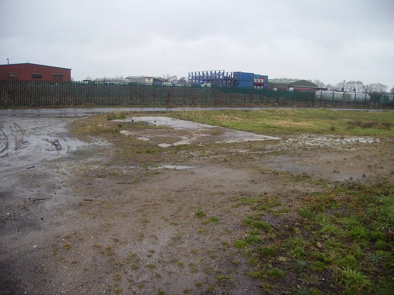
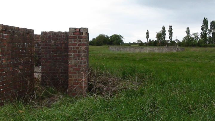
Civil Engineering Compound & Offices Area Foundations Camp 3 2015.
What you can see is the civil engineering compound and offices area.
The rear of the sub station is in the far left background and the
parachute packing house and store is on the far right.
The Fuel & Coke Store.
The fuel and coke store/area as you can see is split into 3 separate bays.
The Back of the Fuel and Coke Store
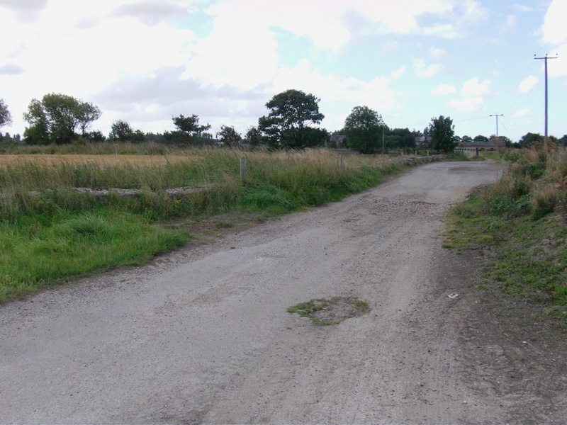
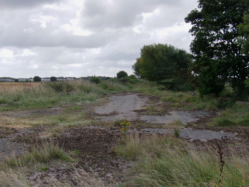
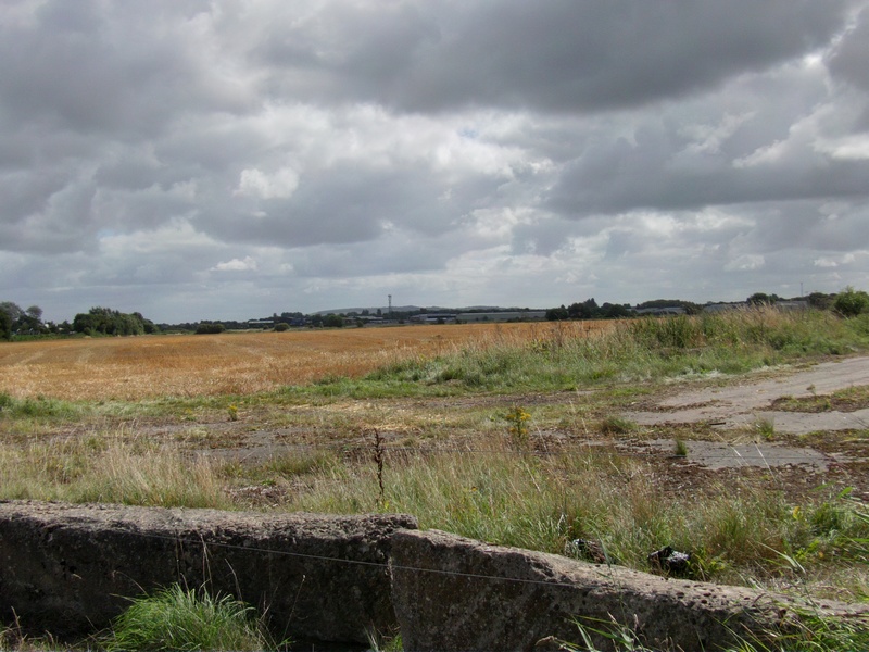
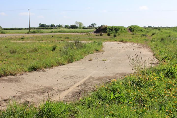
Remains of the North Perimeter Track Facing West (Mike Dawson is just in the Photo)
Continuation of the Remains of the North Perimeter Track Facing West
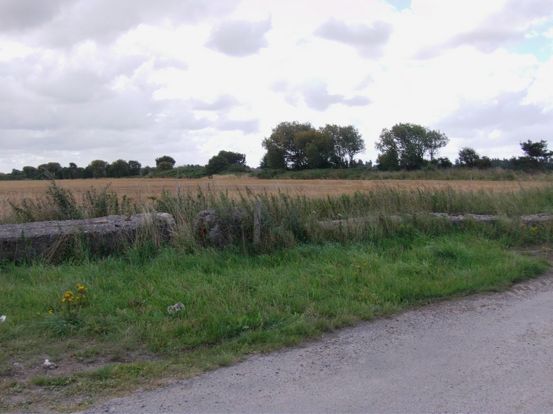
This Can be seen From the Remains of the North Perimeter Track Facing North.
In fact it was taken from the perimeter track looking north.
Continuation of the Remains of the North Perimeter Track Facing West
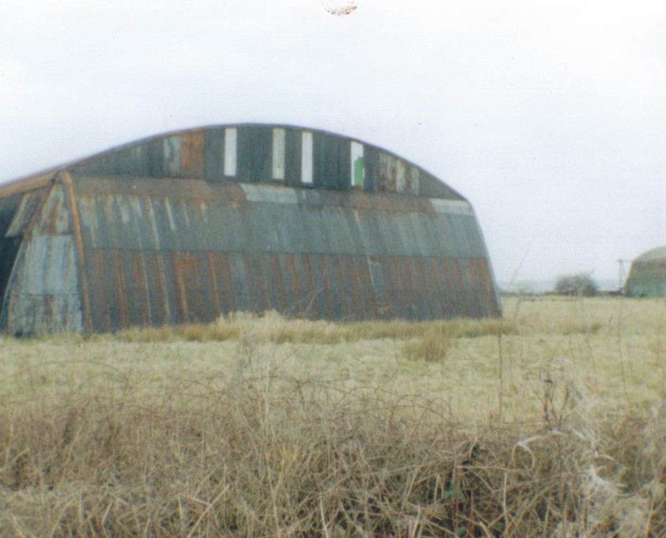
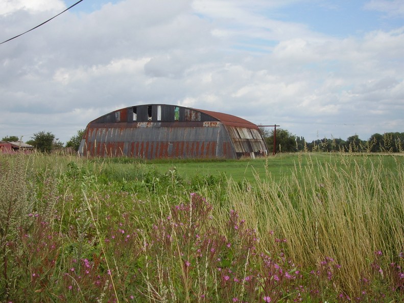
Mainhill Hangar 'S' Shed on the North Facing Side of the North Perimeter track
Continuation on From the Remains of the North Perimeter Track turning
slightly left and in the distance where the tree line is, is the head of runway 17.
The concrete blocks on the left are in the position of runway 12
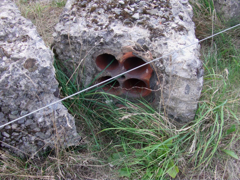
4 Way Stoneware Conduit Electrical Ducts Encased in
Concrete on the head of Runway QDM170 (Runway 17)
Head of Runway 17
The Tree Line (Below) Follows the Route of Runway17
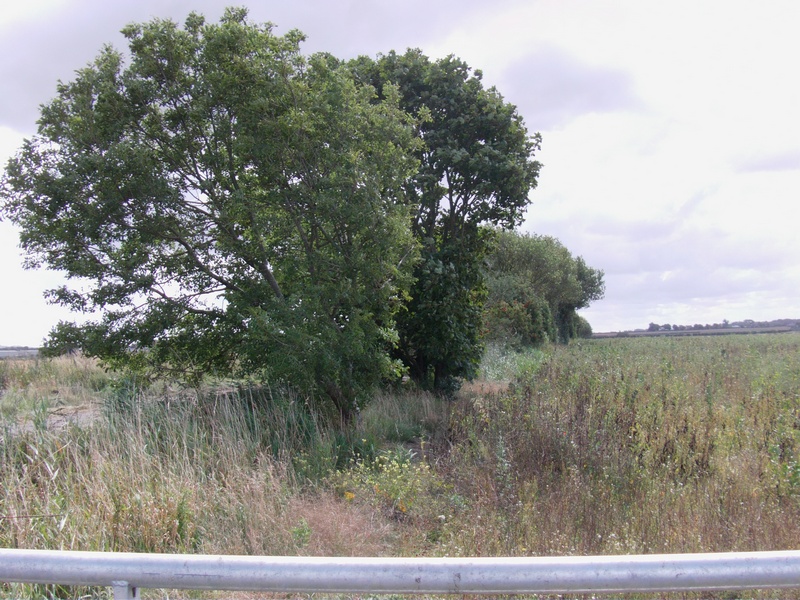
Head of Runway 17
Note: The communication mast just visible in the distance was
next to where the control tower used to be .. (now demolished)
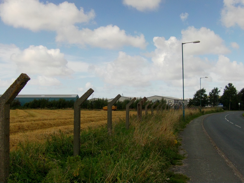
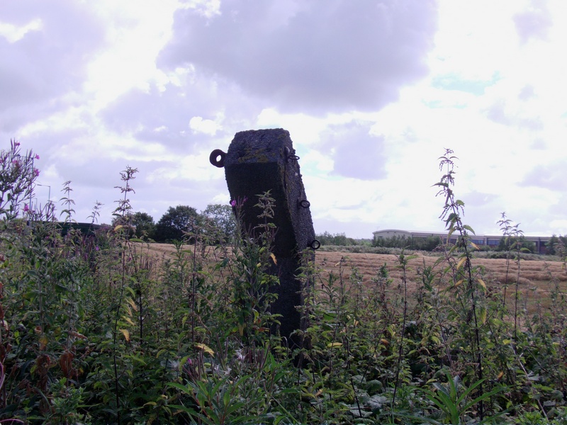
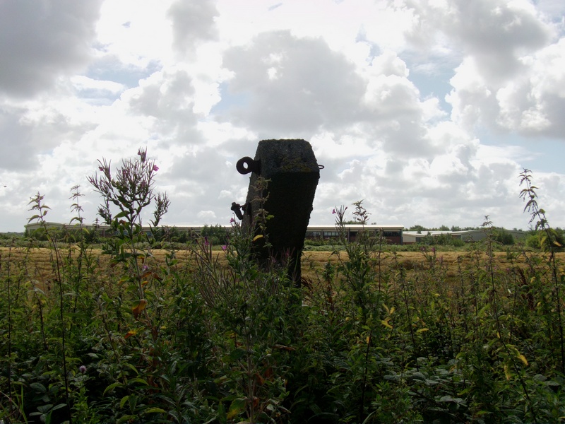
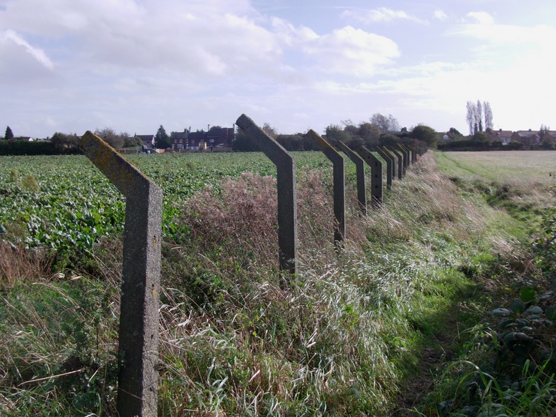
Higgins Lane Perimeter Fence Photos 2014
(at the back of Camp 3)
The thickest post (the 5th post along in the photo) has ratchet
strainers to tension the barbed wire through the other posts.
These thickest posts are at each corner and are also spaced out every 10th post along the length of the actual fence itself and wires would have been fixed on the front (the face that is showing).
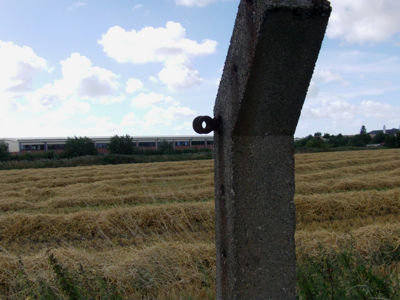
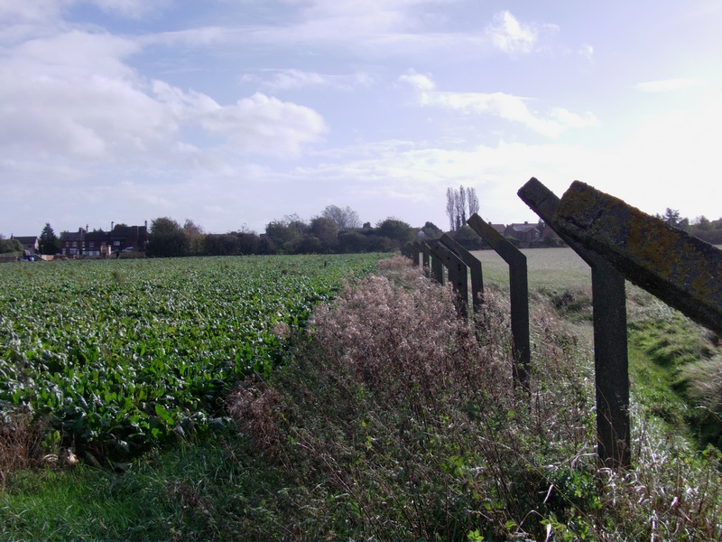
Ratchet Strainer Post
(These are spaced out every 10th post on the perimeter fence)
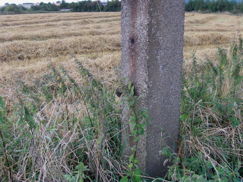
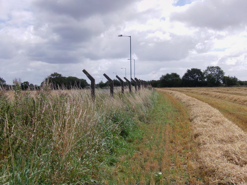
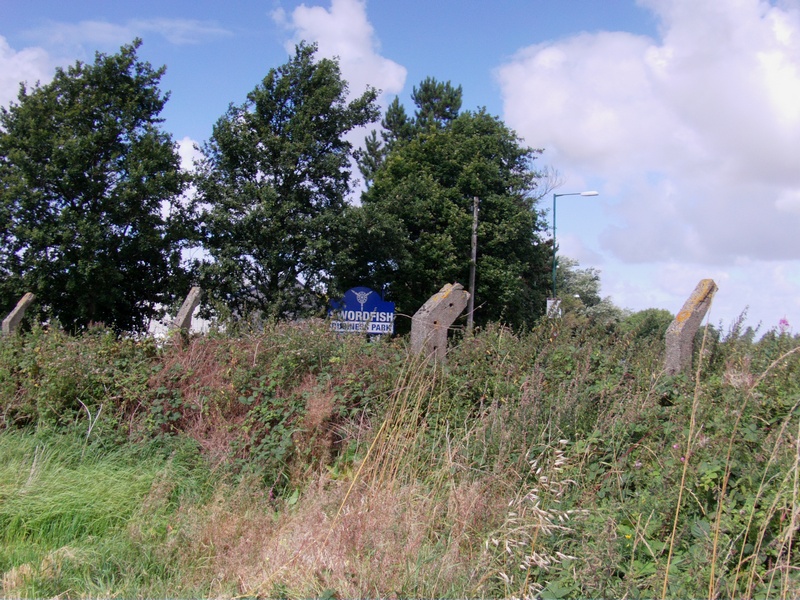
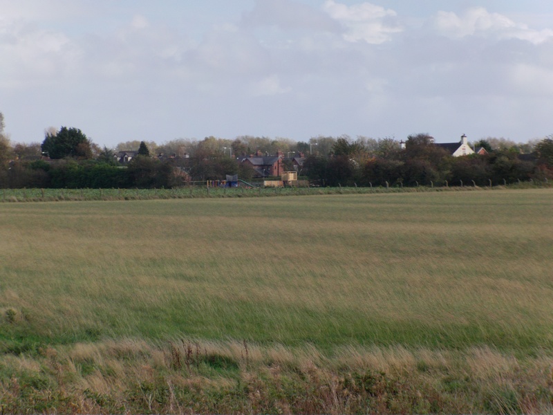
Higgins Lane Perimeter Fence Posts Continued
(Note: The blue sign has a propeller on it and the industrial
park now is called 'Swordfish Business Park')
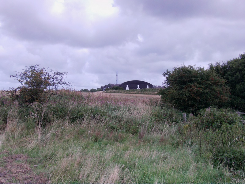
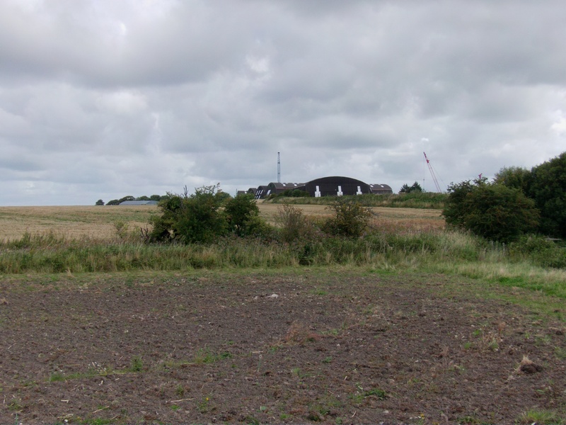
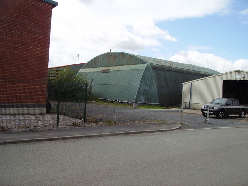
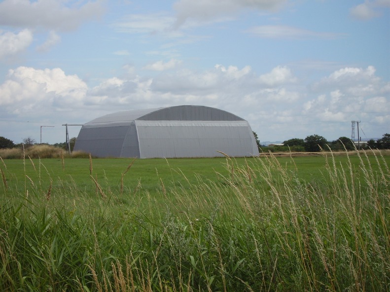
Radar Test Area Hangar 2014
The 3 larger hangars behind are NOT original, although
they are built from other hangars from around the airfield
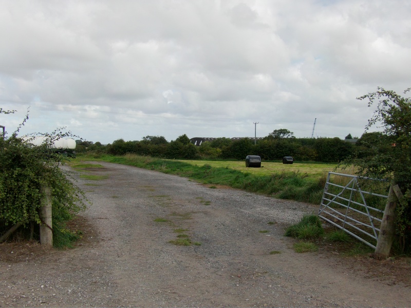
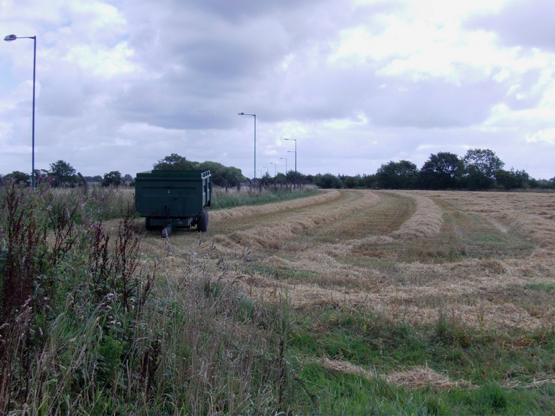
Runway Controllers Van Standing
This is the remains of the exact area where the runway
controllers van standing used to be.
It is situated at the south end of runway 03/21.
Perimeter Fence (Back of Red Lion in the Distance)
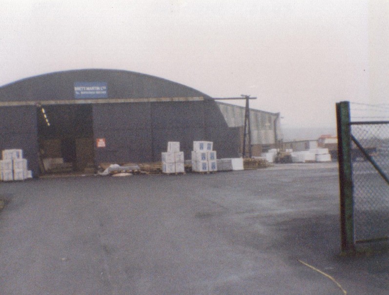
Callender Hamilton Maintenance Hangar 1984
(This is now Firwoods as of 2015)
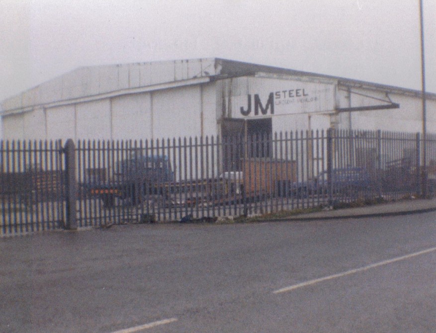
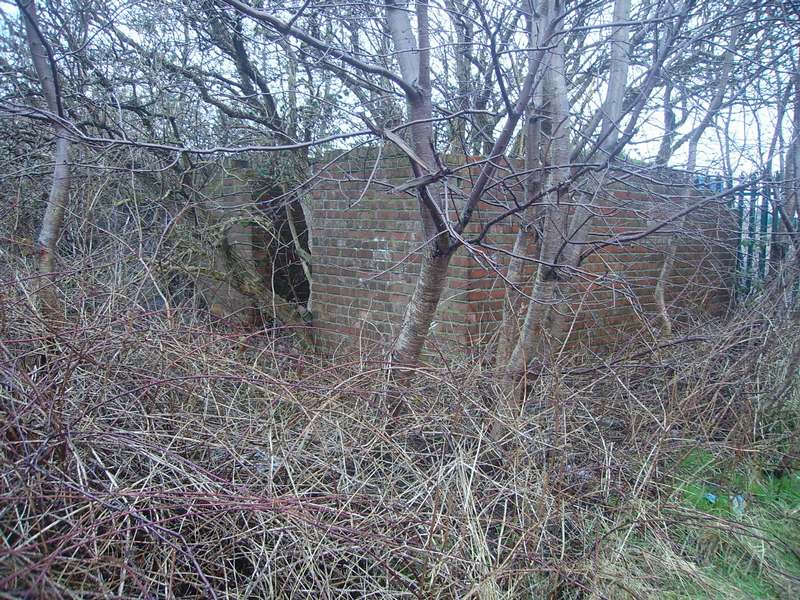
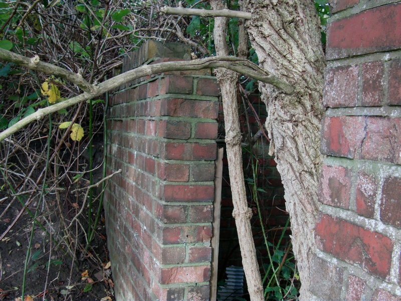
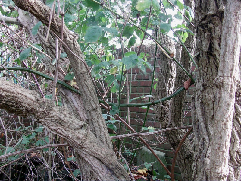
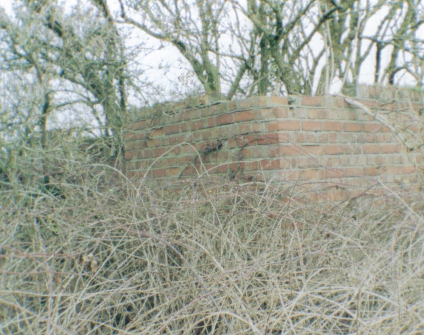
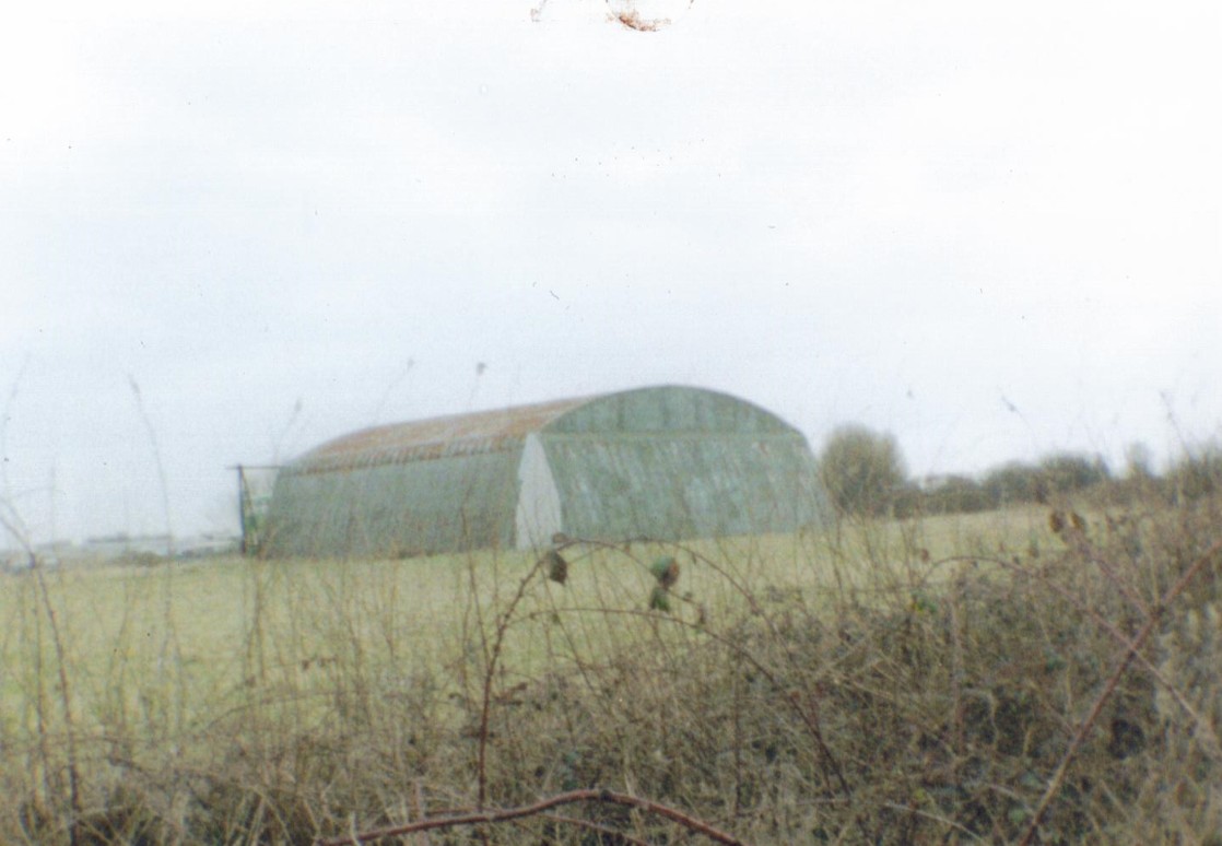
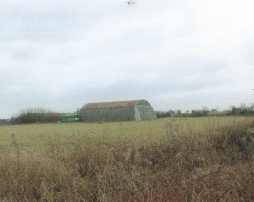
Admiralty 'S' Shed Hangar 1984
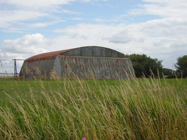
Admiralty 'S' Shed 2014 Close to the Main Gate Was Sited
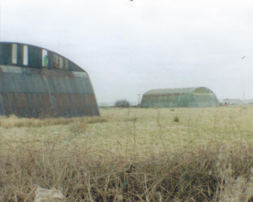
Pippin Street Dispersals 2004
Originally there was 6 mainhill admiralty type 's' hangars.
4 still remain today in their original location on the airfield.
Same Hangar 2013
Pippin Street Dispersals 2004
Same Hangar 2013
Hangar 2013
Pippin Street Dispersals (2014 though now) Continued ...
The building on the left of the photo is listed as a shelter but we think it was an electrical transformer plynth.
In the background is a static water tank/emergency water supply.
Ablution & Laterine Building 2014
An unusual name but this was a bathhouse and toilet block.
Ablution & Laterine Building in 2004
Stubbs Lane Entrance Gate to Pippin St
Dispersal Area (Off Pippin Street) 2004
Stubbs Lane Entrance Gate to Pippin St
Dispersal Area (Off Pippin Street) 2004
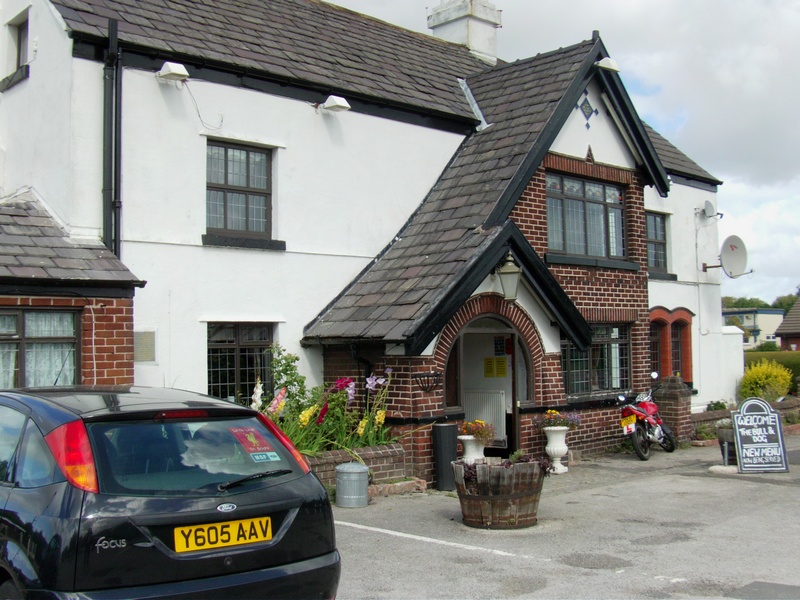
Bull & Dog 2014
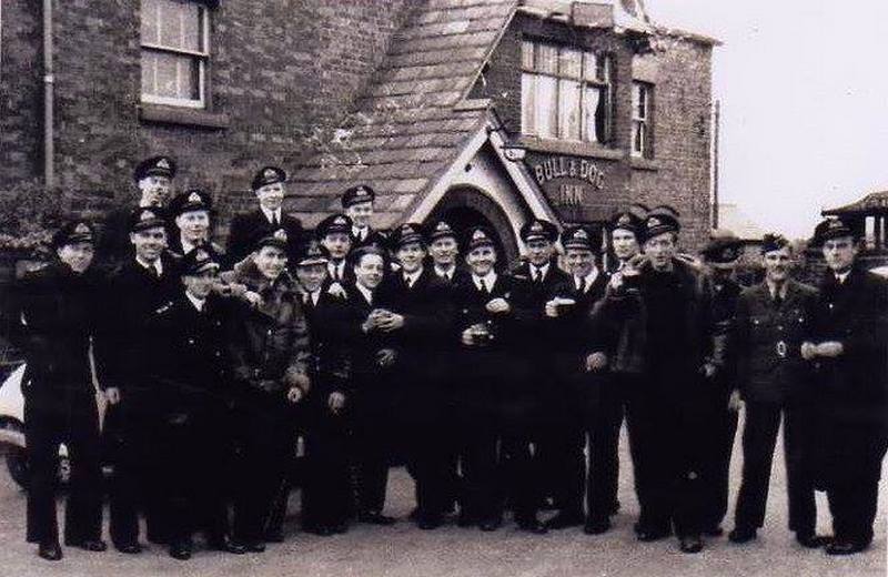
Bull & Dog 1944
1772 Squadron celebrate a 21st Birthday at the Bull and Dog in May 1944.
This Squadron was formed at Burscough on 1st May 1944.
The Bull and Dog was a regular 'haunt' for the Naval Personnel.
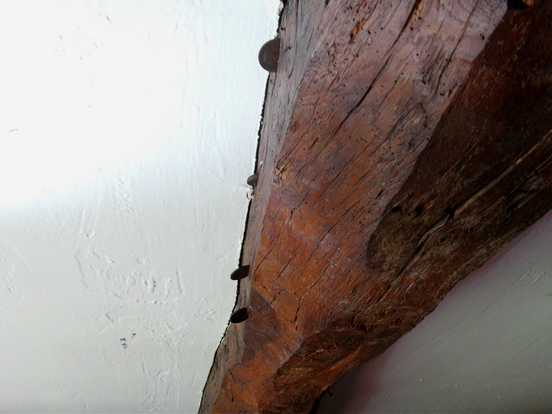
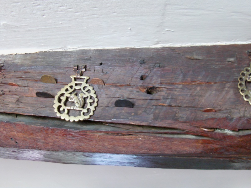
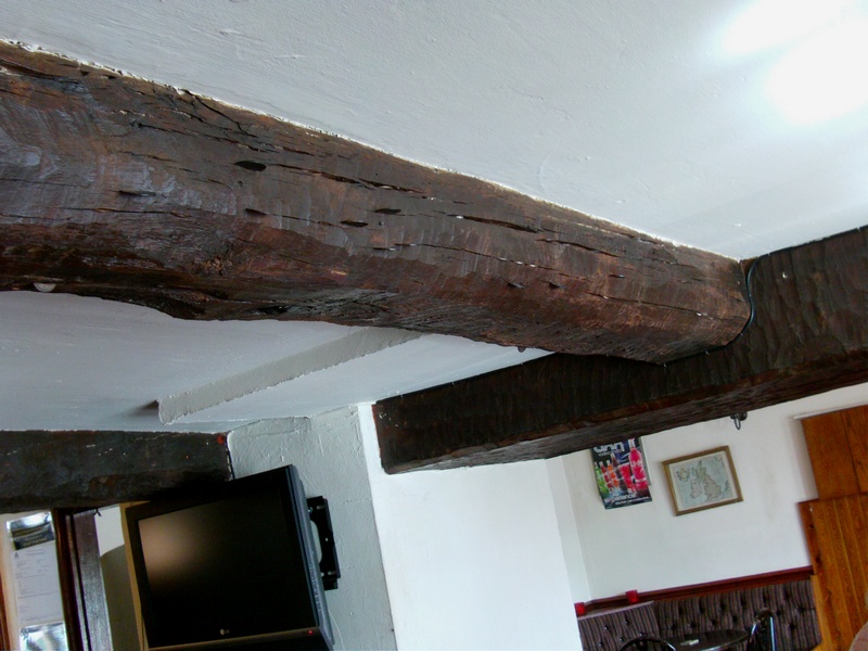
Bull & Dog (Inside) 2014
Royal Naval Personnel had a tradition of inserting coins into the wooden beams
inside the pub ... who knows, it could be some of the guys above?
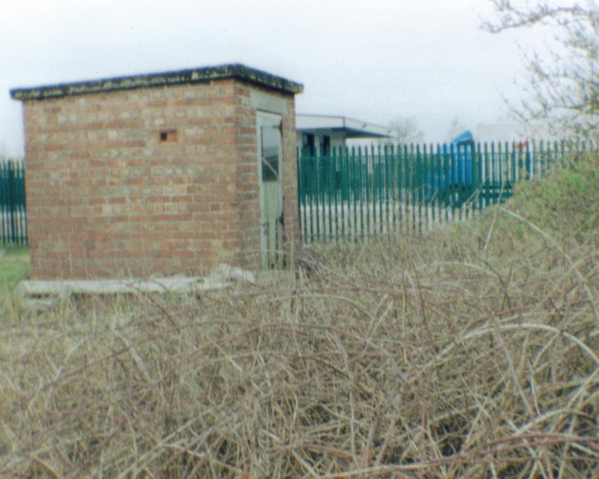
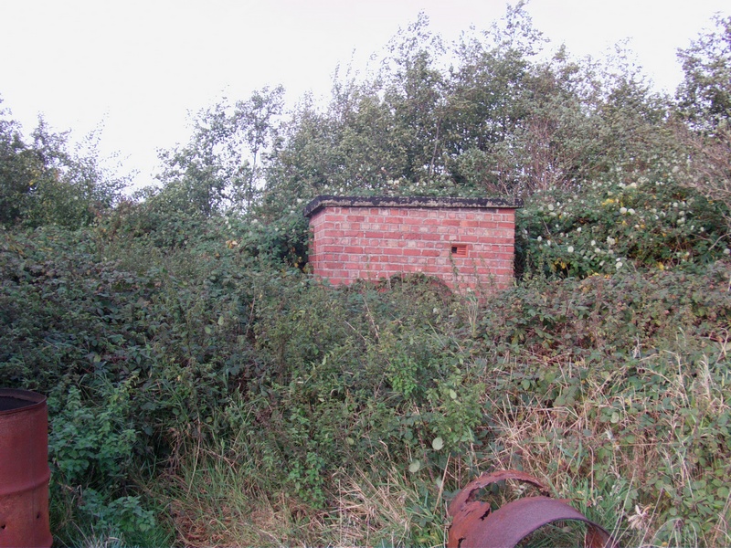
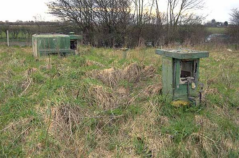
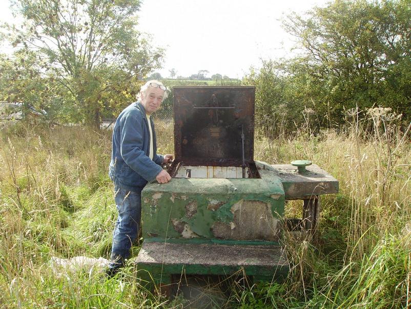
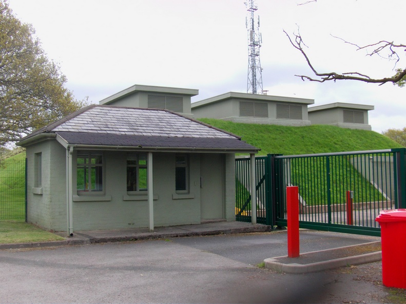
'Cold War' ROC (Royal Observer Corps) Monitoring Post United
Kingdom Warning & Monitoring Organisation Burscough Lancashire.
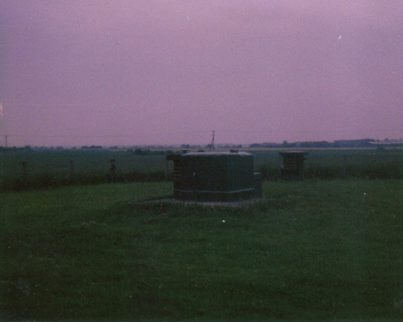
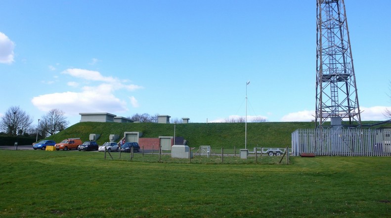
Picture of ROC Post Burscough Taken From a Different
Angle When in Operation During the Cold War in 1984
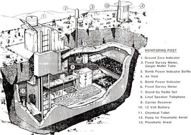
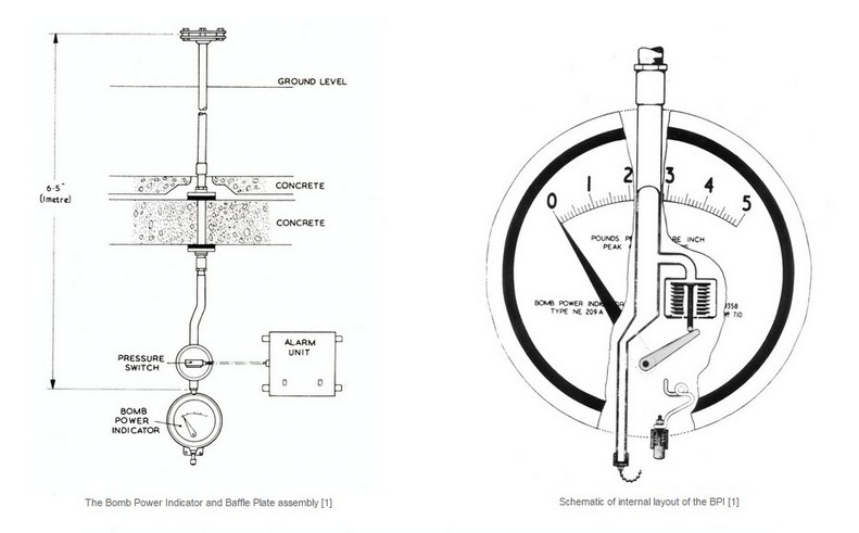
Cutaway Drawing (1) of a Typical Monitoring Post Layout
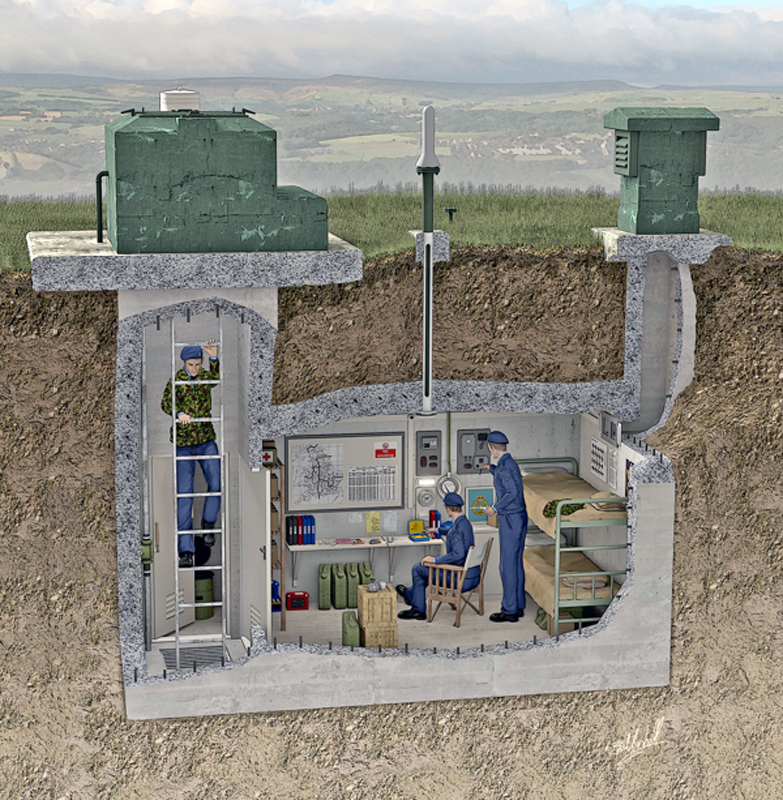
Cutaway Drawing (2) of a Typical Monitoring Post Layout
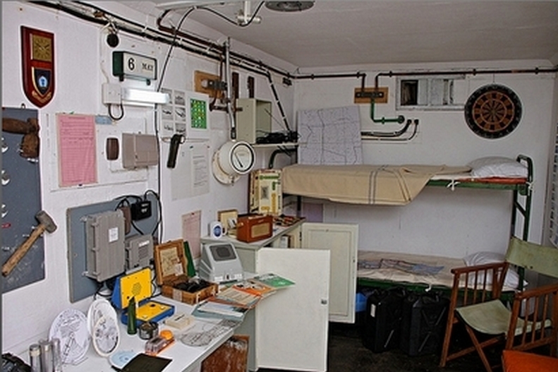
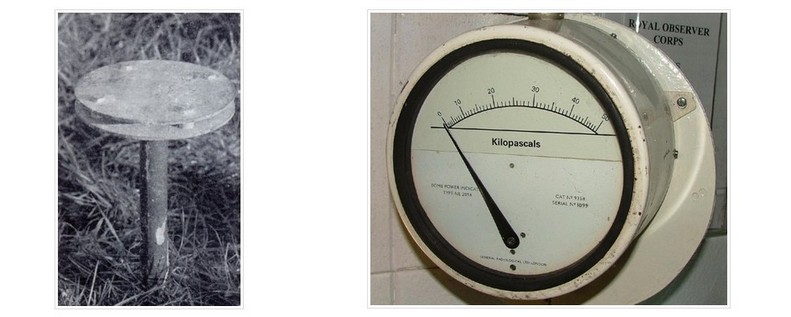
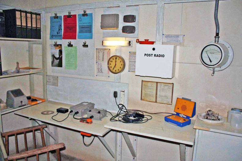
An Example of a Fully Restored ROC Post
(Note: This is NOT Burscough/Ringtail)
The following photos are of the master post No.45 located on Pippin Street on the airfield perimeter in a large square-gated fenced compound. 1,563 of these posts were built throughout the country, 8 square miles apart in clusters of 3 or 4.
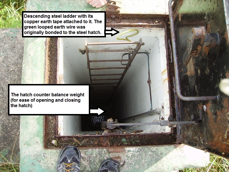
1 post in each cluster being the master post, with a VHF radio. Woodvale & St Helens being in Burscough's cluster. The post opened in April 1962 & closed in September 1991. The entrance hatch leads to a 15 foot vertical ladder down to an underground chamber measuring 7 foot by 16 foot by 7 foot high.
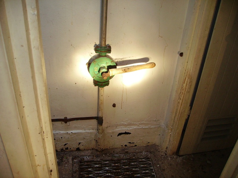
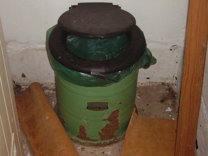
A chemical toilet is located in a small room at the bottom of the entrance ladder.
The main monitoring room houses the 3 observers & their instruments. The cluster was linked by telephone landline to each post in the cluster & group headquarters.
Group headquarters being at 21 group control Langley Lane Goosnargh North of Preston. In the event of the landlines going down the radio master post was used as a back up.
A petrol electric generator set was used in the posts to charge up the batteries for lighting & for the VHF radio.
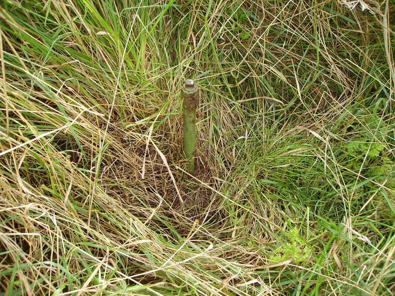
The post instruments consisted of a ground zero indicator sighted on the side of the entrance hatch above ground to record the position & height of a nuclear detonation. This consisted of a 4 pin hole camera in 1 enclosure.
Light sensitive photographic papers recorded the position & size of the fire ball of the bomb.
A bomb power indicator was used to detect the size of the peek pressure of the blast of a nuclear bomb by an above ground baffle plate fed down a pipe to a bomb power indicator meter below ground.
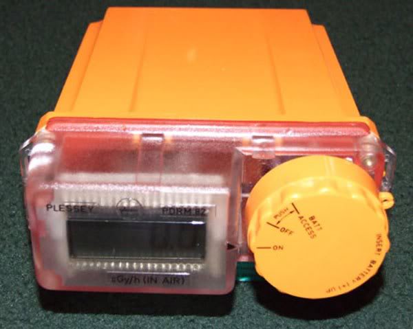
A fixed survey meter for measuring radio active fallout was carried out by using a plessy dose rate meter radiac PDRM 82F from the monitoring room.
A radiac meter head (also known as the guiger muller head) was pushed through a flange in the monitoring room ceiling up a tube to the outside.
The radiac meter head was connected by a coax cable to the radiac PDRM82F meter display.
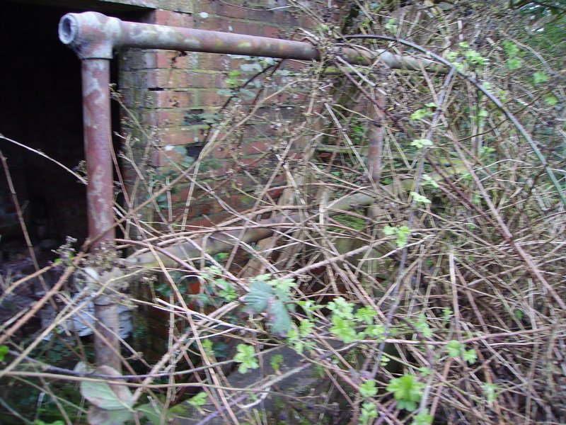
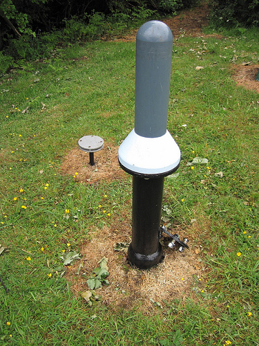
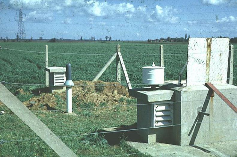
The Ventilation Stack
(The ventilation stack showing the round dome cover for the aerial connections. The round
dome cover is removed to expose the aerial socket when the post is operational)
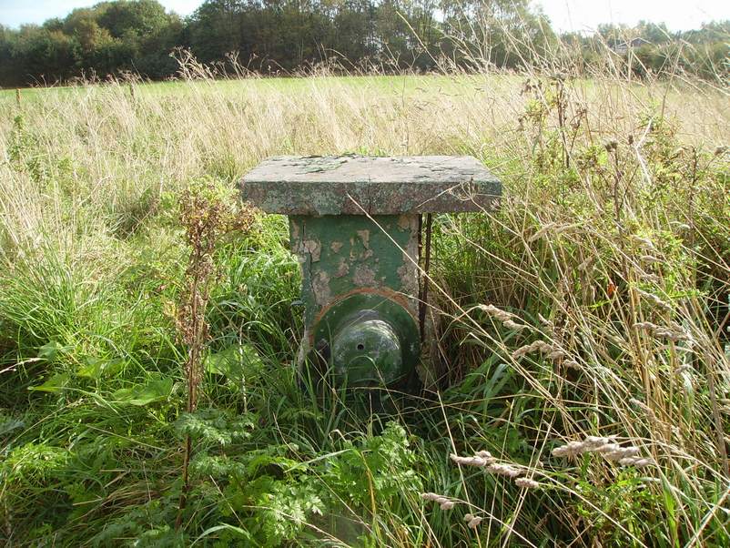
Originally the 2 square apertures were fitted with 2 louvered wooden vents.
To take the dome cover off, there was a tool that was used that was
inserted into the 2 holes to gain access to the aerial conections
Behind The Dome
(This is the view behind the dome. It shows the aerial coax cable
leading down the ventilation shaft to the monitoring room)
Furse copper earth strapping was installed from a ground point a few feet away from the ventilation shaft and was then routed down the ventilation shaft and fitted to all corners of the ceiling below ground and it was also cross bonded to the dome lid cover, the fixed survey meter pipe, bomb power indicator pipe and also the
sump pipe discharge, ladder and had a loop of wire even on the hatch lid.
This was used as a safety measure in case lightning hit the radio mast and potentially killed the occupants.
This is the aerial mast bracket which was originally fitted to the ventilation stack
The aerial was telescopic and could be raised and lowered by an air hose by a foot pump
in the monitoring room. When not in use, the aerial mast was stored
in the entrance shaft next to the ladder.
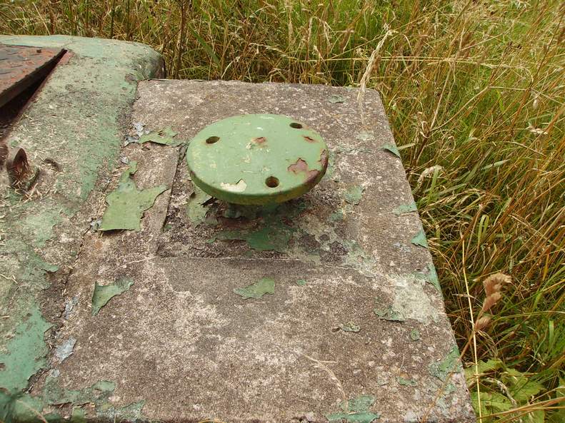
Fixed Survey Meter Pipe
(With its blanking plate fitted)
When the post was operational the blanking plate was removed by unscrewing the 4 bolts and fitted with a polycarbonate dome cover, in which the guiger muller head was then inserted through the roof flange below ground. This was used for measuring radiation fallout readings.
Fixed Survey Meter with Polycarbonate Cover Fitted
(Note: In the background is the bomb power indicator baffle plate)
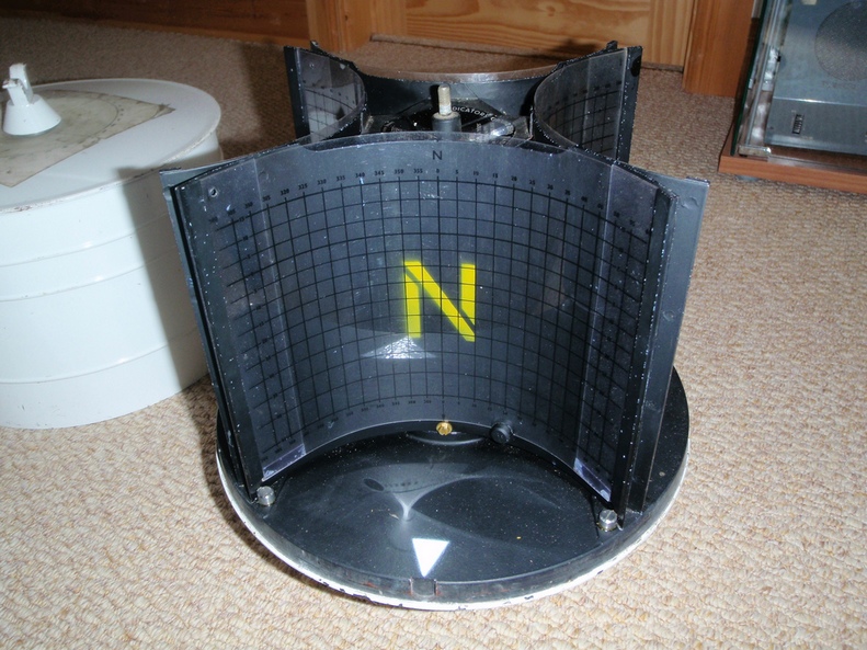
Ground Zero Indicator Mounting Bracket
The ground zero indicator consisted of a 4 pin hole camera with light sensitive photographic paper (called shadow graph) in 4 photographic cassettes and were aligned with the cardinals of the compass to determine the direction and height of a nuclear blast.
Ground Zero Indicator Mounted on Bracket
(Note that you can see 1 of the 4 pin holes)
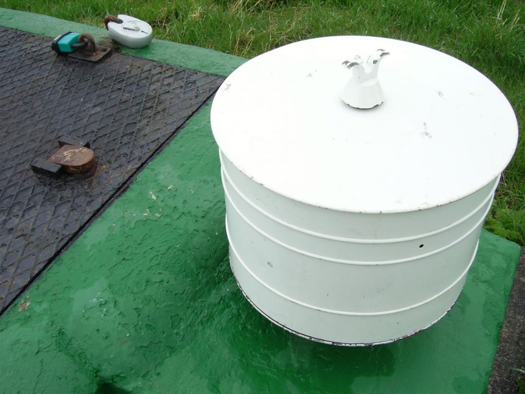
Ground Zero Indicator with its White Cover Removed
Below is the Bomb Power indicator
with it's blanking bolt fitted.
BOMB POWER INDICATOR (BPI)
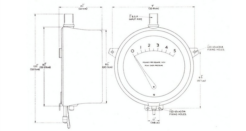
Provided that the distance from ground zero is known, the power of a nuclear weapon can be calculated from the peak over-pressure produced by the blast wave. The Bomb Power Indicator is designed to record this pressure.
External to the monitoring post exists a baffle plate. This baffle plate consists of two metal discs that is screwed onto the top of a pipe that leads down into the underground monitoring post. The over-pressure from a nuclear explosion would be funnelled through the two plates and down the pipe into the monitoring room whereby the over-pressure would be detected on the Bomb Power Indicator (BPI).
The BPI works in the following way:-
The over-pressure from the explosion makes its way down the pipe into the BPI, and is detected by small bellows. One side of the bellows is exposed to normal atmospheric pressure. Attached to the bellows is a push rod which bears against a level fixed to a spindle. When the bellows are expanded, a pointer attached to the spindle moves over a dial reading from either 0 to 5 Pounds per square inch (PSI) or 0 to 50 kilopascals (kPa). The pointer not being actually attached to the bellows, does not return to zero after the passage of the blast wave but is left indicating the peak over-pressure reading. It may then be reset to zero by means of a spring-loaded rod operated by a small push button.
P.E.S. Petrol Electric Set Generator.
The monitoring post had no running water or electrical connection, water was stored in jerry cans in the post.
Electricity for lighting and power for the radio was by 12-volt batteries being charged up by a P.E.S. petrol-electric set.
The P.E.S. was a swan/ Morrison generator consisting of a Villiers four-stroke engine coupled to an alternator direct current.
When the post was not operational the P.E.S. was stored at the bottom of the entrance shaft in the toilet area together with its charging leads.
When the post became operational the P.E.S. was hoisted up the entrance shaft by means of the cargo net /rope.
The observers were told to never store petrol inside the post.
Petrol jerry cans were stored in a refuge pit dug outside of the post within the compound.
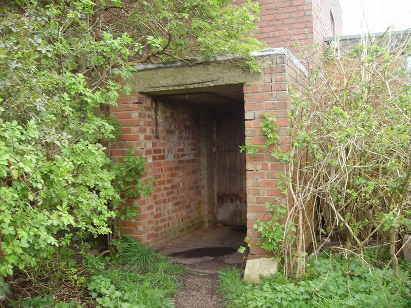
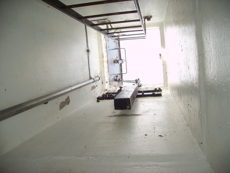
The Monitoring Post Entrance Hatch
View Down The Entrance Hatch
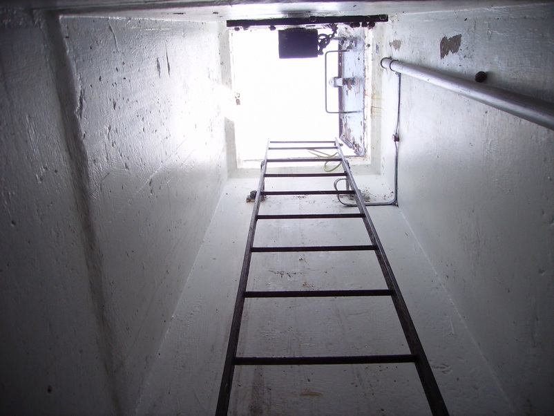
The View Inside The Entrance Shaft Looking Up
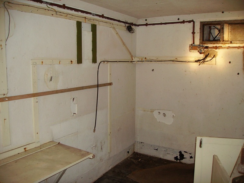
Back Wall View of The Monitoring Room
The Burndept VHF BE525 Radio Transmitter/Receiver Position
The 2 black lines (below) is where the radio cabinet of the Burndept BE525 VHF transmitter radio/receiver was sited. The frequency of Burscough & 21 group was 80.3125 Channel 2 CER, Chanel 3 NWA, Code PRE
(Note the actual aerial lead dangling down underneath the 2 black lines)
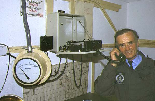
The Burndept VHF BE525 Radio Transmitter/Receiver
osition Actually in Use/Example
Although this is not a photo of Burscough's ROC post, this example shows observer
Harry Wilkinson at 21 group post at Fleetwood actually using the Burndept VHF BE525 radio.
(Note the bomb power indicator at the bottom left with its blast pipe connected from the surface)
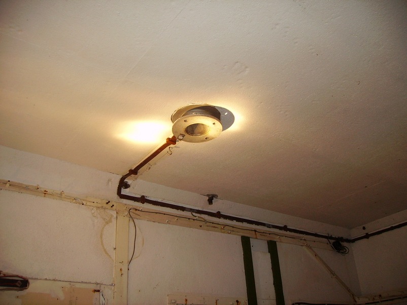
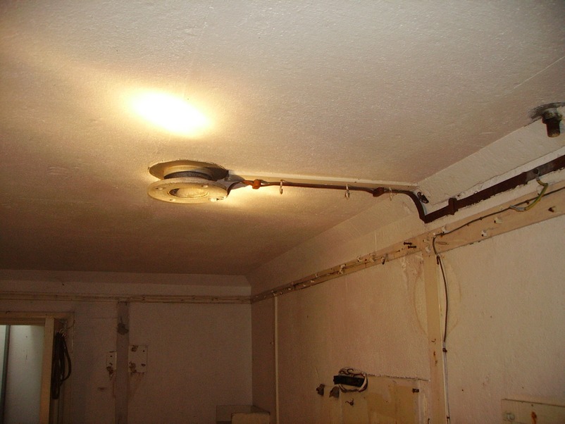
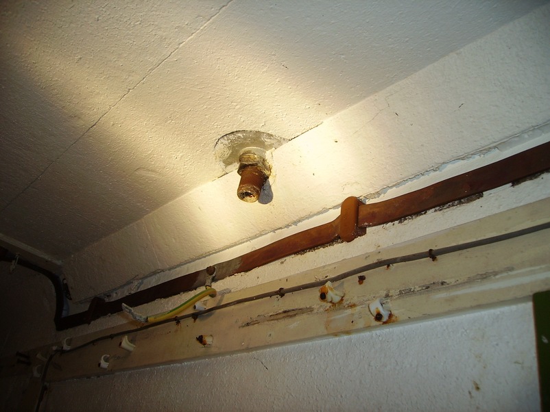
The Fixed Surface Meter Flange
This photo shows the Fixed Surface Meter flange on the ceiling of the monitoring room.
Note the furse copper earth bonding tape connected to it.
The Carrier Warning Receiver (after next photo) was
Sited to The Left above the Monitoring Room Table
WB1401 CARRIER SPEECH WARNING RECEIVER
The WB1401 equipment in the post are armored and waterproof and is normally mounted on a wooden board on the wall of the post above the left-hand end of the post table.
The WB1401 consists of the receiver, Loudspeaker and the line filter unit.
The WB1401 is connected to the post telephone circuit it receives signals and spoken messages which are transmitted at a very high frequency and filtered out of the normal speech traffic before it reaches the L.S.T.or the control telephone system.
The unit has its own battery trickle charged by the line current from the serving telephone exchange.
In the event of a nuclear attack, a high pitched warbling sound would be broadcast over the receiver followed by the spoken message ATTACK WARNING RED repeated three times.
Warning Receiver Instruction Card
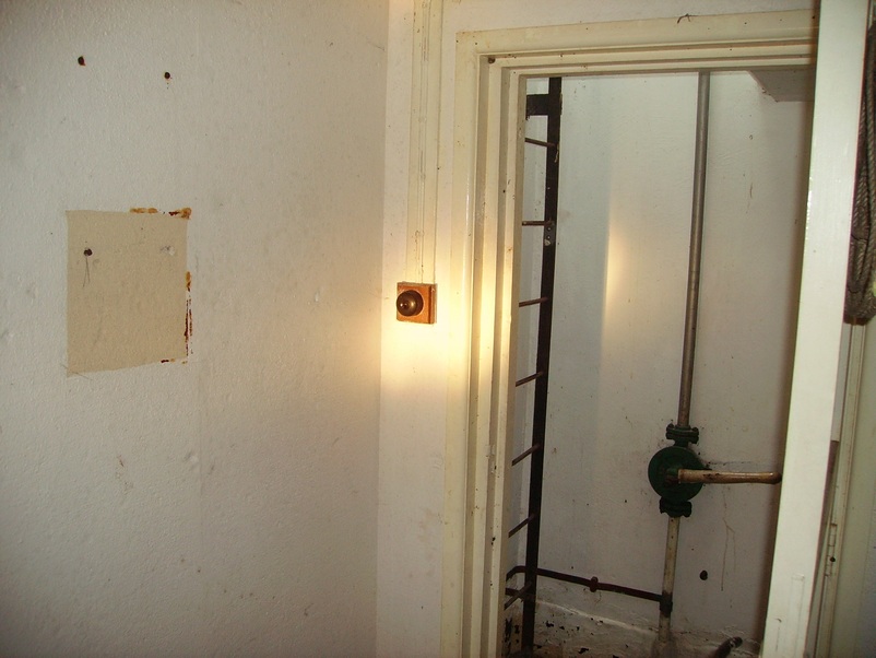
Incoming Landline Connection Point
This is the left hand wall of the monitoring room looking from the door.
The round connection box in the centre of the photo is the incoming telephone landline.
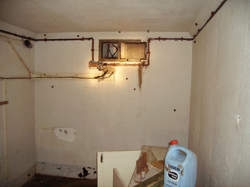
The Air Vent with its Steel Shutter
Note the furse copper Earth tape bonding connection running under and round the sides of the vent.
The bottom earth tape goes through the wall and runs up the ventilation shaft above ground bonding connection. Note also the black cables going through the wall.
These also run up the ventilation shaft and are for the aerial mast.
The View From the Back Wall Towards the Monitoring Room Door
(Turn left through the door to the entrance shaft ladder & turn right to the chemical toilet room.)
Please note: If you look at the desktop/table you can see a rectangular slot in it.
This is roughly where the Plessey Radiac Meter was situated.
The Plessey Radiac Meter PDRM 82F
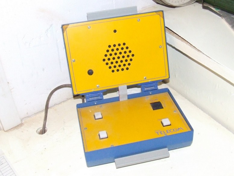
The Teletalk Type AD 8010
Also on the monitoring room table was the loudspeaker telephone and was known as a TeleTalk Type AD 8010 and was connected to a dedicated private land line circuit to 21 group headquarters at Lingley Lane Preston by simply pressing a call button.
The other posts in the cluster could talk amongst themselves without involving group headquarters.
Bomb Power Indicator Blast Pipe Connection Point
Note the green and yellow bonding cable which would have had an earth clamp fitted to the blast pipe
The Monitoring Room Entrance Door View
From Inside the Monitoring Room
The square on the left is where the emergency fire blanket was situated.
The monitoring room light switch is unusual because most post were fitted with a timed light switch.
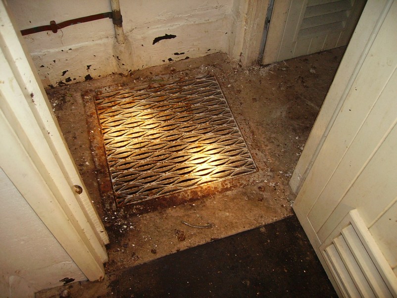
Water Discharge Pump
The photo below is of the water discharge pump. This was used as a hand pump to pump out the water from the sump below the grill (below) to the outside above ground. Note the furse copper earth bonding attached to the pipe at the bottom of the pump.
Close up of The Water Discharge Pump
Close up of the Water Discharge Pump Grill
(The chemical toilet is through the door opening on the right
and to the left is the access ladder to the outside/surface)
The Chemical Toilet
Entrance/Exit Shaft Leading to Outside/Surface
The hatch lid counter balance is the large rectangular weight in the centre of the image. The long pipe coming from the left of the photo is the water sump discharge pipe. Note the furse copper earth bonding tape attached to the discharge pipe and cross-bonded to the steel ladder.
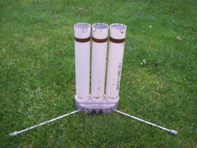
Maroon Rockets
To warn the local public of nuclear fallout radiation, 3 projectile/rockets. known as
'maroon rockets' were sent high into the sky and then exploded making 3 large bangs in quick succession.
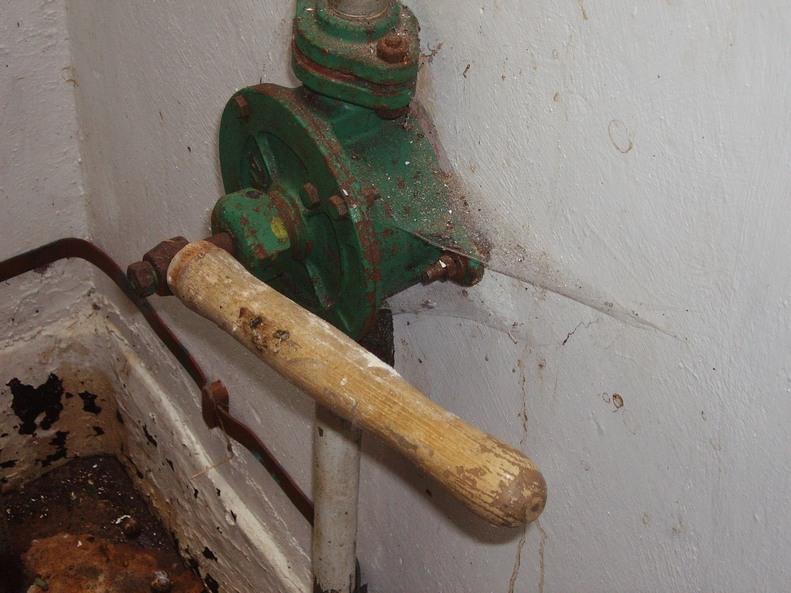
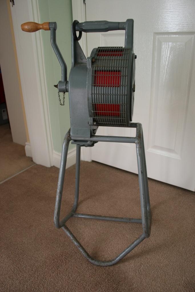
A Hand-Cranked Sekomak 447 Warning Siren
A hand cranked warning siren positioned above ground was sounded to warn the local public of a nuclear
attack. 2 different sounds were used. 1 rising and falling sound was to warn of an attack
and 1 continuous sound was for the all clear.
An Example of an ROC Post Showing Such Features as the Ground Zero Indicator Mounted on the Side of the Hatch & the Fixed Survey Meter with its Polycarbonate Cover Fitted
ROC 21 Group Headquarters & UKWMO National Protected Group Headquarters Langley Lane Goosnargh Preston Lancashire
(The guard room in the foreground dates back to WW2.
Note the 3 huge air exhausts/vents on the roof)
Side view of the bunker
The 100 foot high aerial mast is now used by a communications company.
Note: The site is now owned by a CCTV monitoring company
Regarding the image above, we were confused at first why there would be a (seemingly)
fully functioning ROC post at Goosnargh right next to the main old HQ.
We originally thought that it was there for training purposes but we sent
the query to Nick Catford of Sub Brit and this is his reply:
|
"Hi Gary & Malc
Yes all sorted. This came from Mike Norris of the ROCA at Preston
“The current owner of the control, a security company still maintain an interest in the ROC. In fact the manager allows our ROCA meetings to be held in the former control about every six months, in return we have provided him with various item of memorabilia. The post you see has actually been recreated from parts salvaged from a local post (36 post Catforth/Inskip) which were for a temporary display in a museum. Later transferred to the control, the features on your photograph are only the surface items. A full sized mock up has been recreated inside the control in a former tank room. He has made a quite superb job of this, right down to the battery powered lighting!”
I think that answers it. Below is a photo of the monitoring room they have created in the bunker. I think it looks pretty good. Not sure about the post radio box and of course the carrier receiver and speaker should be mounted on a sheet of chipboard painted grey.
Nick"
|
Built on the former site of the WW2 9 group control, the group HQ opened in January 1962.
To offer a greater level of protection to survive a nuclear attack the bunker was semi sunken into an earth banking. The roof and walls were constructed of 1 metre thick reinforced concrete. The bunker housed state of the art ventilation/heating and filtration plant and 2 standby electric generators.
The main entrance was through 2 gas tight blast doors made of steel and inside the building there were male and female toilets, a canteen, dormitories were also built.
Water tanks were provided for sinks and a decontamination wash room.
The control room collected information from all 21 groups ROC monitoring posts including Burscough's post to establish the location of height power & fallout of a nuclear explosion. The group headquarters close in 1992 and is now used for private commercial use.
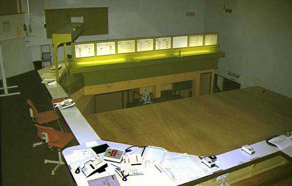
ROC Control Room (When Operational in 1991)
(Photo by Terry Tracey)
|